GrabCAD
Lightweight underrun
by GrabCAD
Last crawled date: 1 year, 10 months ago
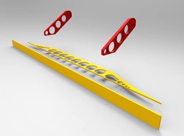
My idea of underrun protection for a truck.
The goal of my design is the lowest possible weight with reasonable manufacturing cost. This is why i've chosen sheet metal design, which should provide enough stiffness with straigth forward manufacturing.
Whole assembly consist of only 3 different parts. Yellow parts (in the renderings of exploded view) are made using laser cutter from 10mm thick steel. Red parts have bigger thickness (30mm), so they would have to be cutted by waterjet . Whole assembly would then be welded together.
Assembly weigth : 44.1 Kg
P1 load case:
Maximal VM stress: 348.7 MPa
Maximal deformation: 9.182 mm
P2 load case:
Maximal VM stress: 353.1 MPa
Maximal deformation: 2.786 mm
P3 load case:
Maximal VM stress: 353.4 MPa
Maximal deformation: 2.315 mm
For analysis I have used the build in FEA plugin in Autodesk Inventor 2014. I have also tried the SimScale "software" but same as others on the market there is a problem with importing of new design iteration. It just takes a lot more time to do it and setup analysis again and again.
PS: About the aesthetic of the design.... Well it's yellow :)
Similar models
grabcad
free

SimScale Truck Underrun Protection Challenge
...imal v.m. stress <355 mpa
maximal deformation - - mm
p3 load case
maximal vm stress < 355 mpa
maximal deformation - - mm
grabcad
free

truck underrun protection
...ding condition,
at load p1- stress (von;mises)-307 mpa , deformation-7.3 mm
at load p2-346 mpa ,3.7 mm
at load p3-170 mpa ,1.9 mm
grabcad
free

Optimized Truck Underrun Protection Device
...se (1.25 mpa applied pressure):
maximum von mises stress: 102.2 mpa
maximum deformation: 0.6701 mm
minimum factor of safety: 3.47
grabcad
free

UNDERRUN Azrul Amir
...96.621 mpa
deformation: 0.0051 m
p2
stress: 335.896 mpa
deformation: 0.0024 m
p3
stress: 215.534 mpa
deformation: 0.0015 m
grabcad
free

Truck Underrun
...a
max displacement 1.281 mm
load case 3:
lowest factor of safety 2.22
max von misses stress 170 mpa
max displacement 1.79 mm
grabcad
free

Underrun Protection_Version DT-D
...nt = 0.534 mm ; max.von mises stess = 186.6 mpa). load case p3 : (max.displacement = 0.537 mm ; max.von mises stress = 97.4 mpa).
grabcad
free

Underrun Protection_Version DT-C
...t = 0.64 mm ; max.von mises stess = 309. 3 mpa). load case p3 : (max.displacement = 1.38 mm ; max.von mises stress = 248.49 mpa).
grabcad
free

Knuckle Joint Analysis
...sing fusion 360, while ansys was employed for the subsequent analysis. the chosen material for this analysis is structural steel.
grabcad
free

UNderrun Protection v4
...55mpa
case p2
displacement – 3,74mm
huber stress (vm) < 355mpa
case p3
displacement – 4,72mm
huber stress (vm) < 355mpa
grabcad
free

SimScale Truck Underrun Challenge
...3 (steel).
i've included a screen shot for load cases p1, p2, and p3 for stress and displacement from the simscale analysis.
Underrun
thingiverse
free

Tamiya Truck underrun guard rear curved
...ar curved
thingiverse
curved underrun guard for the rear of stock tamiya trucks. can be mounted easily on the stock screw holes.
thingiverse
free

Audi TT underrun protection nut by Germanbratwurst
... infill
0,15mm layers
0.4 mm nozzle
i have printed it with flexible filament, but i think it will also works with other materials
thingiverse
free

Burson Conductor v1 usb card upgrade from Tenor TE8802L to XU208 XMOS (Lusya)
...was not clean enough with many clicks/pops audio dropouts/buffer underrun. after finding that not even the original cm6631 card...
thingiverse
free
Ferrex (Aldi) 20V Battery Adapter by Thinger13
...stop discharging before the safe minimum voltage level is underrun the safe minimum voltage per 20v pack may be...
thingiverse
free

Bosch 18V Battery Adapter by Thinger13
...the safe minimum voltage level is underrun. after an underrun the charger may refuse to load the battery or...
grabcad
free

Simscale Truck Underrun
...simscale truck underrun
grabcad
52kg
grabcad
free

Simscale Truck Underrun Challenge
...2 and since cannot run simscale due to low system configuration, simulated in solidworks simulation.
mass of the product : 61 kg
grabcad
free

Curved Truck Underrun
...
thank you to simscale for providing such a fantastic service, i really enjoyed doing the stress analysis simply in the browser.
cg_trader
free

Curved Truck Underrun
...ice, i really enjoyed doing the stress analysis simply in the browser. underrun part truck lamps light vehicle other vehicle part
grabcad
free

Truck Underrun
... load condition
vom mises stress: 247 m pa
deformation: 2mm
under p3 load condition
von mises stress: 216m pa
deformation: 1.1mm
Lightweight
3d_export
$25

glass chair 3D Model
...glass chair 3d model 3dexport comfortable chair lightweight plastic steel metal furniture object design glass chair 3d...
3ddd
$1
Full lamp pack - Birdie - Foscarini
...are designed to scale original manufacturer. birdie combines a lightweight pure and user-friendly design, a strong character. polycarbonate and...
archive3d
free
Luster 3D Model
...luster 3d model archive3d luster chandelier lustre candlelight luster lightweight n081014 - 3d model (*.gsm+*.3ds) for interior 3d...
3ddd
$1

Vitra Suita Three Seater Sofa
...from vitra and antonio citterio that is at once lightweight and technical. the precise geometry and soft padding of...
3d_ocean
$16

Foscarini Lightweight suspension lamp
...gn by tom dixon. the model is based on the manufacturer’s original dimensions and was created paying much attention to all the...
3d_ocean
$89

Mercedes-Benz SLS AMG 2011
...car delivers a compelling mix of purist styling, consistent lightweight design and...
3d_ocean
$5

Pro Light Studio For Cinema4D
...you the best render of your object , its lightweight and professionally textured, like it , and enjoy...
3d_ocean
$5

Torn Cloth
...two versions of the project. -collapsed, the project is lightweight -editable in order to modify the properties of...
3d_ocean
$35
Foscarini - Birdie - Set of 8 Design Lamp HD
...wall lamp, 4 ceiling lamp ) birdie combines a lightweight pure and user-friendly design, a strong...
3d_ocean
$10
Cessna 182 Skylane
...cessna 182 skylane 3docean aircraft airplane cessna flying vehicle lightweight plane plane private propeller skylane model was create with...