GrabCAD
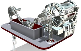
Konecranes chain analyzer
by GrabCAD
Last crawled date: 1 year, 10 months ago
In my design I placed two strain gauges on opposite sides on the water container, both for measuring vertical water displacement.
By using two strain gauges; the top surface of the water can be determined. [If the crane was on an incline this would also be detected]
The strain gauges will be connected to an CU. [The CU is also connected to the Orbital wire conductors, on the rollers, for phase change synchronization]
The CU will detect any unusual resistance changes in the amplitude of the sine waves, when the strain gauge encounters a deficiency of a chain]
[This solution offers a real time dynamical volume measurement, with little processing power]
Water principle:
A superhydrophobe can be used on the chain and pulley system, were it will be emerged in water. This would cause a minimal interaction between the water and the surface material. [During R&D you should check if air bubbles are in the ridges, if there are try using normal hydrophobe]
To overcome evaporation of the water, I propose to use a ionic compound to keep evaporation to a minimum. Also it would lower the freezing temperature and could be used at low temperatures. [Anti freeze could be such ionic compound]
Strain gauge principle:
The strain gauge is glued on to a waterproof sheet. This sheet is glued to an aerogel or sponge material, that can be compressed when water presses against it. [The top of the aerogel or sponge material is not sealed, so that gas pressure can rapidly change]
The top of the strain gauge is restricted, so that it can experience an bending moment from the changing water pressure. [Also the conductance will change]
Orbital wire conductors principle:
On two rollers I have placed on each: two conducting rings. One ring on the front and the other on the rear. These rings are connected with conducting wire trough a channel in the roller. [The electrical signal passes from the CU, to the rear rod, to the rear orbital ring, trough the channel in the roller, to the front orbital ring, trough the front rod, and back into the CU.]
On the front ring there is also a gap. This gap causes the electrical signal to fall to zero when it is directly over the connecting rod. This can be used to determine the phase change in both rollers. [Which in turn can be used to measure the length of the chain section between the two rollers]
[Load cells]:
To get extremely high accuracy in my design, I offer optional load cells. These load cells would give the density for each chain. Also with the load cells, the CU could calculate how much the roller cylinders are bent. Which would cause the error of margin to become even smaller in determining the length of a chain section. [These load cells are connected via the Orbital rings. But instead of just one ring, each load cell has it's own orbital. There would be six rear Orbital rings, six load cells, and six front Orbital rings. This is where the use of the Orbital comes to light. The load cells are almost continuously able to give an electrical signal to the CU. Only during the gap there is no signal]
Budget:
€ 5.00 ~ Water container
€20.00 ~ 2 strain gauges [stain gauge + restrictor + earogel or sponge]
http://www.alibaba.com/trade/search?fsb=y&IndexArea=product_en&CatId=&SearchText=strain+gauge
http://www.alibaba.com/trade/search?fsb=y&IndexArea=product_en&CatId=&SearchText=aerogel
€10.00 ~ superhydrophobe
http://www.alibaba.com/trade/search?fsb=y&IndexArea=product_en&CatId=&SearchText=super+hydrophobic
€ 5.00 ~ conducting wire
€10.00 ~ control unit
[http://www.alibaba.com/trade/search?fsb=y&IndexArea=product_en&CatId=&SearchText=microcontroller]
Production costs below 50€ or ~$65 USD.
[without load cells]
http://www.alibaba.com/trade/search?fsb=y&IndexArea=product_en&CatId=&SearchText=strain+gauge+load+cell
margin of error:
Strain Gauges [volume measure] ±0.5%
a) Cracks
b) Serve nicks or gouges
c) Visible distortion
e) Deposits which cannot be removed
g) If interlink wear leaves a rough surface, this indicates that rapid wear is occurring and the chain should be rejected immediately
Superhydrophobe layer chain ±0.1%
d) Severe corrosion
Orbital wire conduction ±0.5% [optional load cells ±0.1%]
f) The gauge length measured over an 5, 7, 9 or 11 links as appropriate exceeds that of the unused chain by 2% if power driven
A note: I have considered using Magnetostriction, Piezoelectricity and Photon detection methods. But these solutions seem to fall into geometric computability problems. [Also the budget would need to be larger]
Similar models
thingiverse
free

SHS Steel Square Tube by abrokadabra
...ections-c_49.html
purchase here:https://www.alibaba.com/trade/search?fsb=y&indexarea=product_en&catid=&searchtext=shs
grabcad
free

Console strain gauge with load cell
...console strain gauge with load cell
grabcad
console strain gauge with load cell alfa gl-50 www.alfainstrumentos.com.br
grabcad
free

5kg Strain gauge load cell
...5kg strain gauge load cell
grabcad
5kg strain gauge load cell, used for aircraft electric thrust stand model
thingiverse
free

Strain Gauge Load Cell Bracket by clevtool
... load cell from moving, so a crude version of that is included.
load cells found at: https://www.amazon.com/gp/product/b079ftxr7y
thingiverse
free

Strain Gauge Load Cell Bracket by arretx
...t and through whatever it's mounted on if the electronics are located on the opposite side of the flat surface for the scale.
grabcad
free

Hx711
...hx711
grabcad
the hx711 load cell amplifier is used to get measurable data out from a load cell and strain gauge.
grabcad
free

Cantilever strain gauge with lower nether application
...
grabcad
cantilever strain gauge with lower load application v2.0 with double nether cell alfa gl-50 www.alfainstrumentos.com.br
thingiverse
free

Knife sharpener
...8mm lenght aprox. 350mm (https://www.aliexpress.com/wholesale?catid=0&initiative_id=sb_20191116021759&searchtext=rod+8mm)
grabcad
free

TAL-220 straight bar load cell
...mm, 250mm wire
https://www.sparkfun.com/products/13329
https://cdn.sparkfun.com/datasheets/sensors/forceflex/tal220m4m5update.pdf
grabcad
free

Load Cell 830 Low Profile Strain Guage
...load cell 830 low profile strain guage
grabcad
the low profile strain gauge is 25.95 mm x 29.95 mm x 1 mm
Konecranes
grabcad
free

KoneCrane Trailer
...konecrane trailer
grabcad
trailer customized for client
grabcad
free

Konecranes
...konecranes
grabcad
konecranes
grabcad
free

Konecranes Chain Wear Indicator Challenge
...ould be some faults in these models, i'm just learning to use this software, and this is one of my first models and desings:)
grabcad
free

Konecranes challenges
...konecranes challenges
grabcad
see word file
grabcad
free

Konecranes LOGO
...konecranes logo
grabcad
potentially useful for konecranes challenge
grabcad
free

Konecrane crane with X-Ray Camera
... locked so it cannot be used until the chain is serviced.
this way every failure mode can be captured with one detection method.
3dwarehouse
free

Konecranes Gottwald GHMK6 Mobile Harbor Cranes
...nes gottwald ghmk6 mobile harbor cranes
3dwarehouse
this is a low poly model of a konecranes gottwald g hmk6 mobile harbor crane
Analyzer
3d_ocean
$7

Detergent Bottle 900 ml
...th rhinoceros. getting high detail and perfect curves on complex surfaces. surfaces analyzed with diagnostic tools and ‘zebra’...
3d_ocean
$7

Detergent Bottle 750 ml
...th rhinoceros. getting high detail and perfect curves on complex surfaces. surfaces analyzed with diagnostic tools and ‘zebra’...
cg_studio
$15

Alcohol Breathalyser3d model
...alcohol breathalyser3d model cgstudio alcohol analyzer breathalyzer breathalyser blood device machine test screening breath lcd...
3d_export
$15

Alcohol Breathalyser 3D Model
...alcohol breathalyser 3d model 3dexport alcohol analyzer breathalyzer breathalyser blood device machine test screening breath lcd...
3d_export
$20
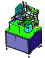
power cord adhesive tape machine
...anipulator: 0.005 mm, repeated positioning accuracy of manipulator: ≤ ± 0.01 mm, and material change mode: manual material change
3d_export
$7
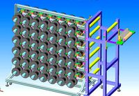
wire and wire copper axis fpc adhesive tape laser cutting peeling cutting machine - final assembly
... learn a lot. i won't introduce other details here. the above is the whole structure and working principle of this equipment.
3d_export
$74

Best Local solar companies in US
...xpert installers and expert elect ricans. the system has been doing the job to perfection as it was put in one particular yr ago.
3d_export
$80

us army m1130 command vehicle stryker cv with detailed interior max obj
...g 3d models with superior quality. customized modeling service/format translation/additional tech support available upon request.
3d_export
$69
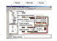
v-eleq electrical control simulation software
...rol circuit. at the same time, it can also demonstrate and analyze various faults in the wiring process through visual simulation
thingiverse
free

Mamo Vu-Meter (14 Band Spectrum Analyzer) by Mamo
...rs should be enough)
280 plexiglas plates 40x20 mm saw cut (no laser) (i took 300)
electrical cable
m3 screws and nuts
controller
Chain
3d_export
$45

4 Bearing Collection 3D Model
...industrial thrust spherical radial machinery race cage collection set chain 4 bearing collection 3d model 3dillustration 24788...
3ddd
$1

Currey & Company Balthazar
...per light: 60 total wattage: 180 bulb type: candelabra chain length: 6 feet item wt: 11 pkg wt: 16...
3ddd
$1

Currey & Company Orion
...per light: 25 total wattage: 300 bulb type: candelabra chain length: 6 feet freight information: motor freight item wt:...
3d_ocean
$79

Peugeout AF01 (Rigged)
...in original size. full rig: -handelbare -brakes -chainring + chain +rare wheel -and more… hi res textures including psd...
3d_export
$15
Modern Crystal Chandelier 3D Model
...crystal modern aluminium ceiling glass diamond light lighting lamp chain modern crystal chandelier 3d model download .c4d .max .obj...
3d_export
$30

Cognac sigar Set 3D Model
...glasses cigar guillotine almonds carafe bottle zhitkost whiskey glass chain cigarettes tobacco nuts brandy acohol cognac sigar set 3d...
3d_export
$15

Toothpick Holder 3D Model
...clean oral pick casing holder case tube carry key chain toothpick holder 3d model download .c4d .max .obj .fbx...
3ddd
$1

подвес Kichler Lighting 2666ACO
...base incandescent light bulbs included: no wiring type: hardwire chain length: 36...
3ddd
$1
One Kings Lane Hemispheres Chandelier
...glow above any dining table. size: 32"dia x 51"h chain length: 3'l the model is based on the original...
3ddd
$1
Arteriors Monty Chandelier
...creates a subtle lighting effect on the ceiling. additional chain available chn-995. the model is based on the original...
