Cults

Jet Engine, Geared Turbofan (GTF)
by Cults
Last crawled date: 6 years, 1 month ago
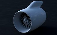
Jet Engine; Geared Turbofan (GTF)
For the latest jet engine for passenger planes, the Bypass Ratio is bigger and bigger to improve the engine-performance.
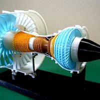
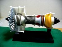
In order for one of them, the Geared Turbofan (GTF) is developed. 3D model for explaining this system was designed and made imaging "PW1000 series engine.
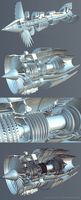
The points of the design are;
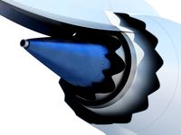
Compact "Fan Drive Gear System" which has 3 to 1 Reduction Ratio. (shown by color "RED" in photos)
For the rotation of each spool, the ball bearing method and the dummy bearing method are prepared.
All stator vanes are omitted this time, because of avoiding rub of vanes and blades. And each rotor except LPT is designed with support so that it can be printed as one-piece.
The blade angle is made to agree in the spool rotational direction (View from Rear).
HP Spool: Clockwise
LP Spool: Counterclockwise
Fan: Clockwise
In addition, some parts that printing is considered difficult without support, are prepared STL file with support. The last of two digits of the file name is identified as "ws". In order to ease understanding about the contents of each part and the assembly order, parts breakdown and list are prepared.
Download files includes;
-files: STL Files
-images: Parts Breakdown for assembly Aid
-Excel File: Parts List
Purchase Parts Information;
-Bearings (Can be used Dummy BRGs instead of the followings, See Parts List)
DDL-1370ZZ (7 x 13 x 4) 2ea - For LP-Spool
689ZZ (9 x 17 x 5) 3ea - For HP-Spool and Fan
675ZZ (5 x 8 x 2.5) 2ea - Fan Drive Gear Train
-Aluminum Tubes
See Parts List
-Screws
Micro screws M1.4x3L - Appox. 60 ea - Direct screw-in to 1 mm dia hole (No nut),
Screws M2 x 6L - 4 ea, See Parts List
Screws M3 x 8L and Washer - 1 ea, See Parts List
Assembly Points
Standard Skill (such as Drilling, Tapping, Filing, Tightening, Painting and Gluing etc) is needed and perseverance too.
For gears: Deburring (removing the sharp edges etc.) is very important for smooth rotation.
HPC and LPC rotor: Take care when removing the support from the blades.
Total Net Print Time: Approx. 31HR
(Estimated as case of PLA, 0.4mm Nozzle, 0.2mm Layer Height, 40% infill and No raft and support)
Note: When at actual print, each parameter should be adjusted by your experience.
For the latest jet engine for passenger planes, the Bypass Ratio is bigger and bigger to improve the engine-performance.
In order for one of them, the Geared Turbofan (GTF) is developed. 3D model for explaining this system was designed and made imaging "PW1000 series engine.
The points of the design are;
Compact "Fan Drive Gear System" which has 3 to 1 Reduction Ratio. (shown by color "RED" in photos)
For the rotation of each spool, the ball bearing method and the dummy bearing method are prepared.
All stator vanes are omitted this time, because of avoiding rub of vanes and blades. And each rotor except LPT is designed with support so that it can be printed as one-piece.
The blade angle is made to agree in the spool rotational direction (View from Rear).
HP Spool: Clockwise
LP Spool: Counterclockwise
Fan: Clockwise
In addition, some parts that printing is considered difficult without support, are prepared STL file with support. The last of two digits of the file name is identified as "ws". In order to ease understanding about the contents of each part and the assembly order, parts breakdown and list are prepared.
Download files includes;
-files: STL Files
-images: Parts Breakdown for assembly Aid
-Excel File: Parts List
Purchase Parts Information;
-Bearings (Can be used Dummy BRGs instead of the followings, See Parts List)
DDL-1370ZZ (7 x 13 x 4) 2ea - For LP-Spool
689ZZ (9 x 17 x 5) 3ea - For HP-Spool and Fan
675ZZ (5 x 8 x 2.5) 2ea - Fan Drive Gear Train
-Aluminum Tubes
See Parts List
-Screws
Micro screws M1.4x3L - Appox. 60 ea - Direct screw-in to 1 mm dia hole (No nut),
Screws M2 x 6L - 4 ea, See Parts List
Screws M3 x 8L and Washer - 1 ea, See Parts List
Assembly Points
Standard Skill (such as Drilling, Tapping, Filing, Tightening, Painting and Gluing etc) is needed and perseverance too.
For gears: Deburring (removing the sharp edges etc.) is very important for smooth rotation.
HPC and LPC rotor: Take care when removing the support from the blades.
Total Net Print Time: Approx. 31HR
(Estimated as case of PLA, 0.4mm Nozzle, 0.2mm Layer Height, 40% infill and No raft and support)
Note: When at actual print, each parameter should be adjusted by your experience.
Similar models
thingiverse
free

Jet Engine, Geared Turbofan (GTF) by konchan77
...f you are interest it, please refer the following url.https://cults3d.com/en/3d-model/tool/geared-turbofan-engine-gtf-10-inch-fan
cults
free
Jet Engine, 3-Spool
...0.4mm nozzle, 0.2mm layer height, 40% infill and no raft and support)
note: when at actual print, each parameter may be adjusted.
cults
free

Jet Engine, 2-Spool, Current
... layer height, 40% infill and no raft and support)
note: when at actual print, each parameter may be adjusted by your experience.
thingiverse
free

Jet Engine, 3-Spool by konchan77
...ploaded - 2020.5.19
no support rotors "ipc-rotor101" & "hpc-rotor101" are added as reference. - 2020.6.24
thingiverse
free
Jet Engine, 2-Spool, Current by konchan77
...l print, each parameter may be adjusted by your experience.
[update]
rotor; https://www.thingiverse.com/thing:2835643 - 2018.3.22
cults
free

Jet Engine; Geared Turbofan (GTF), Optional-Fan
...ost printing:
- take care to remove the special support for damaging of the blade.
- finish blade edges and surfaces as required.
cults
$5

Jet Engine, Single-Spool with AfterBurner
...
price discount
[update 2017.12.14]
for "non-shrouded turbine blades rotor", stl file (3), photo and image are added.
thingiverse
free

Jet Engine; Geared Turbofan (GTF), Optional-Fan by konchan77
...rt
post printing:
take care to remove the special support for damaging of the blade.
finish blade edges and surfaces as required.
cults
free

Jet Engine; 3-Spool, Optional-Fan
...rt)
- fan-blade-new-ccw01ws.stl (original: fan-blade201ws.stl)
- note: fan-shaft01.stl and lp-front-stop101.stl are not changed.
3dwarehouse
free

sketchyphysics2 turbofan/jet engine
...an/jet engine
3dwarehouse
sketchyphysics2 turbofan jet #blade #car #fan #gear #jet #sketchyphysics #toad #toads #turbo #turbofan
Gtf
3d_export
$209
pw gtf geared turbofan engine
... in this model, please do not hesitate to contact us, we are looking forward to continuously dealing with you.<br>markos 3d
3d_export
$10

fighter plane
...plane 116 557 polygons 72 773 verts .blend and glb/gtf ...
3d_export
$229

pw gtf geared turbofan engine - cutaway
...y problem in this model, please do not hesitate to contact us, we are looking forward to continuously dealing with you. markos 3d
thingiverse
free
Dew GTF printed parts by wildfrog
...dew gtf printed parts by wildfrog
thingiverse
tpu parts for the dew gtf frame.
thingiverse
free

Platform for GTF by Pickettdew
...platform for gtf by pickettdew
thingiverse
printed to use supports from gtf model https://www.thingiverse.com/thing:2462343
thingiverse
free

Canvas Medal Box by GTFS
...;t know if the premium wood tokens will fit, but if it needs adjusting just leave a comment and i'll try and get round to it!
thingiverse
free
Jet Engine; Geared Turbofan (GTF), Optional-Fan by konchan77
...rt
post printing:
take care to remove the special support for damaging of the blade.
finish blade edges and surfaces as required.
thingiverse
free

Jet Engine; Geared Turbofan (GTF), Modified Parts by konchan77
...the special support for damaging of the blade.
finish blade edges and surfaces as required.
i hope your work to be much improved.
thingiverse
free
Jet Engine, 2-Spool, Current by konchan77
..."geared" turbofan engine models was designed and made.https://www.thingiverse.com/thing:2437217 (3-spool)https://www.thingiverse.com/thing:2462343 (gtf the points of the design are; for the rotation...
thingiverse
free

Printrbot Simple Metal Blower Mount by rwjamieson
...it doesn't draw more than about .4a of current. https://www.aliexpress.com/item/gtf-75mm-x-30mm-dc-12v-0-36a-2pin-computer-pc-blower-cooling-fan/32665460063.html?spm=a2g0s.9042311.0.0.x9b0qz the other fan mounts i found all keep the...
Turbofan
cg_studio
free

Jet engine FREE3d model
...jet engine free3d model cgstudio airbus turbofan aircraft engine cfmi compressor fan pratt military air jet...
3d_ocean
$4
Basic Jet Engine
...engine 3docean a380 basic engine flying jet jumbo plane turbofan vehicle basic jet engine with a few internal components....
3d_ocean
$55
Turbofan Engine
...turbofan engine
3docean
3d engine model plane rocket rotation turbofan
turbofan engine modeler from real blueprints.
3d_export
$79
Cessna 560 Citation V 3D Model
...3d model 3dexport cessna citation 560 five ultra encore turbofanpowered small-to-medium business jet corporate vlj aircraft plane realistic mental...
3d_export
$8
General Electric GEnx turbofan jet engine 3D Model
...engine 3d model
3dexport
jet engine boeing aircraft turbo
general electric genx turbofan jet engine 3d model tasal 60160 3dexport
3d_export
$209
pw gtf geared turbofan engine
... in this model, please do not hesitate to contact us, we are looking forward to continuously dealing with you.<br>markos 3d
3d_export
$5
Fairchild Republic A-10 Thunderbolt attack plane
...the fairchild republic a-10 thunderbolt ii is a single-seat, twin-turbofan straight-wing, subsonic attack aircraft developed for the united states...
3d_export
$25

jet engine cfm56 international
...engine (1:10 and 1:15).<br>3d print model.<br>cfm56 is a high-bypass turbofan engine (most of the air accelerated by the fan...
3d_export
$5
General Dynamics F-111 Aardvark jet fighter
...several technologies for production aircraft, including variable-sweep wings, afterburning turbofan engines, and automated terrain-following radar for low-level, high-speed flight....
3d_export
$60

fairchild republic a-10 thunderbolt ii
...fairchild republic a-10 thunderbolt ii is a single-seat, twin turbofan engine, straight wing jet aircraft developed by fairchild-republic for...
Jet
3d_export
$85
JAS 39 Gripen Jet 3D Model
...ipen jet 3d model
3dexport
aircraft airplane fighter military attack jet
jas 39 gripen jet 3d model vanishingpoint 72995 3dexport
3d_export
$65
News Helicopter 3D Model
...news helicopter 3d model 3dexport aircraft airplane commercial jet airliner civilian flight vehicle transportation helicopter news r44 news...
3d_export
$40

Cessna citation cj4 3D Model
...cessna citation cj4 3d model 3dexport airplane jet aircraft bussines plane private civilian wings cessna citation cj4...
3d_export
$95

Falcon3D A319 United Airlines 2 3D Model
...airplane aircraft airliner plane transport commercial passenger modern twin jet civil civilian a320 a321 a318 a319 airbus falcon3d a319...
3d_export
$95

Falcon3D A340 600 Pacific Charters 3D Model
...plane transport commercial passenger modern twin jet civil civilian jetiner a340 a-340 a-340-600 a340-600 airbus falcon3d a340 600 pacific...
3d_export
$95

Falcon3D MD 80 Hawaiian 3D Model
...freight cargo corporate mcdonnell douglas us plane planes jet jetiner md-80 falcon3d md 80 hawaiian 3d model falcon3d 73148...
3d_export
$65

Aircraft 737 3D Model
...aircraft 737 3d model 3dexport aircraft airplane commercial jet airliner civilian flight vehicle transportation aircraft 737 3d model...
3d_export
$95

Falcon3D MD 80 Fast Cargo 3D Model
...freight cargo corporate mcdonnell douglas us plane planes jet jetiner md-80 falcon3d md 80 fast cargo 3d model falcon3d...
3d_export
$50
Bell 407 Jetranger 3D Model
...e commercial jet airliner civilian flight vehicle transportation helicopter
bell 407 jetranger 3d model digimation 73228 3dexport
3d_export
$85
Tempest 3D Model
...tempest 3d model 3dexport aircraft airplane fighter military attack jet british england raf tempest 3d model vanishingpoint 73000...
Geared
3d_export
$99

Watch 9 3D Model
...ch constantin swiss geneve gears mechanical isochronism parts chronograph exploded people
watch 9 3d model fabelar 81285 3dexport
3d_ocean
$6
f-16 war plane
...f-16 war plane
3docean
f-16 f16 fly plane war war plane
no landing gear low poly ,
3d_ocean
$3

Gears 4
...nical parts process steampunk vehicle wheel work
10 different gear models volume 31-40 files: .3ds .c4d .obj note: you need vray
3d_ocean
$19

Samsung Gear VR innovator s6 edition
...smax, it includes a galaxy s6 edge phone model textures and uvs are included so you can custumize it in your favorite image ed...
3d_export
$49

Samsung Gear Fit Orange 3D Model
...king metrics hand
samsung gear fit orange 3d model download .c4d .max .obj .fbx .ma .lwo .3ds .3dm .stl humster3d 103801 3dexport
3d_export
$10
Gear 3D Model
...ism evolvent shaft wheel key
gear 3d model download .c4d .max .obj .fbx .ma .lwo .3ds .3dm .stl kazankindima20220 104036 3dexport
3d_export
$27
Decorative nautical helm 3D Model
...ive voyage journey
decorative nautical helm 3d model download .c4d .max .obj .fbx .ma .lwo .3ds .3dm .stl deanora 104141 3dexport
3d_export
$10

Wall Clock Gear Kare Design 3D Model
...oft design
wall clock gear kare design 3d model download .c4d .max .obj .fbx .ma .lwo .3ds .3dm .stl valeriya9103 113577 3dexport
3d_export
$49

Samsung Gear 2 Neo Charcoal Black 3D Model
... motion
samsung gear 2 neo charcoal black 3d model download .c4d .max .obj .fbx .ma .lwo .3ds .3dm .stl humster3d 104557 3dexport
3d_export
$849

Watch mechanisms coll 7 3D Model
...iscount save bundle
watch mechanisms coll 7 3d model download .c4d .max .obj .fbx .ma .lwo .3ds .3dm .stl fabelar 111630 3dexport
Engine
3d_export
$10

Wooden Pallet Low Poly 3D Model
...props lowpoly industrial wood 3d unity udk unreal games engine detailed wooden wooden pallet low poly 3d model turcpaul...
3d_export
$10

Old Pallet Low Poly 3D Model
...lowpoly industrial wood old 3d unity udk unreal games engine detailed fbx obg 3ds old pallet low poly 3d...
3d_export
$40

Turboprop twin engine 3D Model
...boprop twin engine plane airplane civilian commercial passenger medium range
turboprop twin engine 3d model tartino 7205 3dexport
3d_export
$29

Female cyborg 3D Model
...bot machine female woman bionic metalic android human science enginering technology future metal fantasy technics sci-fi female cyborg 3d...
3d_export
$75
Falcon3D C414 Chancellor Bare Metal 3D Model
...civil general aviation executive transport charter professional place twin engine propeller commercial ambulance falcon3d c414 chancellor bare metal 3d...
3d_export
$85

Falcon3D C414 Chancellor F02 3D Model
...civil general aviation executive transport charter professional place twin engine propeller commercial ambulance falcon3d c414 chancellor f02 3d model...
3d_export
$15
Classic Steam Train 3D Model
...steam train 3d model 3dexport antique black classic coal engine historic historical iron locomotive metal old power rail railroad...
3d_export
$45

4 Bearing Collection 3D Model
...ballbearing roller ball tapered bearing skf needle engineering gearbox engine car industrial thrust spherical radial machinery race cage collection...
3d_export
$100

2011 Hyundai Verna 3D Model
...hyundai verna sonata tucson avante tuscani genesis gamma gasoline engine coupe sports korean 3dken 2011 hyundai verna 3d model...
3d_ocean
$69
T-34/85 Interior/Engine Bay Full Winter Camo
...nterior and engine bay. the model contains a highly detailed interior(controls, gauges, machine gun, ammo, radio, main gun) an...