GrabCAD

Jet Engine With Afterburner Model
by GrabCAD
Last crawled date: 1 year, 10 months ago
This jet model consists of:
1. Front frame containing VIGV’s ( http://armyaviation.tpub.com/AL0993/AL09930260.htm )
https://grabcad.com/library/jet-engine-s-variable-inlet-guide-vanes-vigv-1 ,
2. Compressor unit, it consists of 13 stage compressor and stator unit having outlet guide vanes at the end
( http://en.wikipedia.org/wiki/Axial_compressor ) ,
3. Diffuser which contains the liquid fuel nozzles here the mixture of fuel compressed air is passed on to the combustion chamber,
4. Combustion chambers, it consists of 8 chambers connected together with cross fire tubes and allows the flames to travel between all of them. Out of 8 chambers 2 have the igniter plugs.
5. Turbine unit, it consists of 3 stage turbine and nozzle unit. Now, when the high-temperature high-pressure gas enters a turbine, where it expands down to the exhaust pressure, producing a shaft work output in the process. The turbine shaft work is used to drive the compressor and other devices such as an electric generator that may be coupled to the shaft. The purpose of nozzles is to direct the gases on the turbine blades.
6. Rear bearing housing, it consists of thermocouples that are used to measure the exhaust gas temperature.
7. After burner unit, it consists of fuel unit, igniter, jet pipe and the nozzle unit. The fuel unit consists of fuel lines and 21 fuel injector nozzles which injects the fuel in the jet pipe where the exhaust gases containing the remaining oxygen burns.
( https://grabcad.com/library/after-burner-nozzle-thrust-vectoring-nozzle-1 )
YouTube - https://www.youtube.com/channel/UCzFRwBLs5z_HmyOp_jiPKNg
Similar models
grabcad
free

Mini jet engine
...s meaning the fuel is introduced into
the chamber against the flow of compressed air. a few major dimensions are mentioned below:
grabcad
free

JET ENGINE
...applications. they have played a crucial role in modern aviation, allowing for faster and more efficient travel across the globe.
grabcad
free

TURBO JET ENGINE
...ling nozzle. the gas turbine has an air inlet which includes inlet guide vanes, a compressor, a combustion chamber, and a turbine
grabcad
free

Turbojet engine
...e turbine. the turbine exhaust is then expanded in the propelling nozzle where it is accelerated to high speed to provide thrust.
grabcad
free

Jet Engine
... the model can then be refined with additional details and features such as air inlets, cooling systems, and structural supports.
grabcad
free

Model Jet Turbine
...
single-stage radial compressor, axial turbine, with annular combustion chamber and vaporiser.
diesel fuel + approx. 10% petrol
grabcad
free

Viper 8 Jet Engine Compressor Assembly
...h turns to run the compressor and other accessories. finally the high temperature, high velocity air exits the exhaust as thrust.
grabcad
free

Core engine assembly for CFM56
...nd rotor blades which represent the high pressure compressor (hpc),combustion chamber assembly,1 stage of high pressure turbine.
grabcad
free

Gas Turbine
...r it
energy is then added by spraying fuel into the air and igniting it so that the combustion generates a high-temperature flow
grabcad
free

Jet Engine's Variable Inlet Guide Vanes - VIGV
...ps://grabcad.com/library/jet-engine-with-afterburner-model-1
youtube - https://www.youtube.com/channel/uczfrwbls5z_hmyop_jipkng
Afterburner
3d_export
$38

Jet Plane Explosion 3D Model
...losion fireball afterburn aircraft fire special effect environment fx
jet plane explosion 3d model rahman.najafian 87888 3dexport
3d_export
$5
Sukhoi SU-75 Checkmate
...version with wheels and 2 flying versions with trails, afterburner pilot and armament.<br>model has bump map, roughness map and...
3d_export
$5
North American XB-70 Valkyrie
...version with wheels and 2 flying versions with trails, afterburner pilot and armament.<br>model has bump map, roughness map and...
3d_export
$5
Lockheed C-5 Galaxy
...version with wheels and 2 flying versions with trails, afterburner pilot and armament.<br>model has bump map, roughness map and...
3d_export
$5
Fairchild Republic A-10 Thunderbolt attack plane
...version with wheels and 2 flying versions with trails, afterburner pilot and armament. model has bump map, roughness map...
3d_export
$5

LTV A-7 Corsair II lowpoly attack plane
...version with wheels and 2 flying versions with trails, afterburner pilot and armament. model has bump map, roughness map...
3d_export
$5

Panavia thunder generic concept lowpoly bomber
...version with wheels and 2 flying versions with trails, afterburner pilot and armament. model has bump map, roughness map...
3d_export
$5

Northrop Grumman B-2 Spirit stealth bomber
...version with wheels and 2 flying versions with trails, afterburner pilot and armament. model has bump map, roughness map...
3d_export
$60

myasishchev m-50
...e two inner engines were located under the wing and the two outer on the wingtips of its shoulder-mounted, truncated delta wings.
3d_export
$5
Mig-29 fulcrum jet fighter lowpoly
...version with wheels and 2 flying versions with trails, afterburner pilot and armament. model has bump map, roughness map...
Jet
3d_export
$85
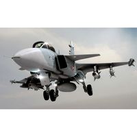
JAS 39 Gripen Jet 3D Model
...ipen jet 3d model
3dexport
aircraft airplane fighter military attack jet
jas 39 gripen jet 3d model vanishingpoint 72995 3dexport
3d_export
$65
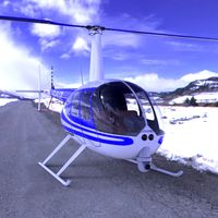
News Helicopter 3D Model
...news helicopter 3d model 3dexport aircraft airplane commercial jet airliner civilian flight vehicle transportation helicopter news r44 news...
3d_export
$40
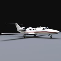
Cessna citation cj4 3D Model
...cessna citation cj4 3d model 3dexport airplane jet aircraft bussines plane private civilian wings cessna citation cj4...
3d_export
$95

Falcon3D A319 United Airlines 2 3D Model
...airplane aircraft airliner plane transport commercial passenger modern twin jet civil civilian a320 a321 a318 a319 airbus falcon3d a319...
3d_export
$95

Falcon3D A340 600 Pacific Charters 3D Model
...plane transport commercial passenger modern twin jet civil civilian jetiner a340 a-340 a-340-600 a340-600 airbus falcon3d a340 600 pacific...
3d_export
$95
Falcon3D MD 80 Hawaiian 3D Model
...freight cargo corporate mcdonnell douglas us plane planes jet jetiner md-80 falcon3d md 80 hawaiian 3d model falcon3d 73148...
3d_export
$65
Aircraft 737 3D Model
...aircraft 737 3d model 3dexport aircraft airplane commercial jet airliner civilian flight vehicle transportation aircraft 737 3d model...
3d_export
$95
Falcon3D MD 80 Fast Cargo 3D Model
...freight cargo corporate mcdonnell douglas us plane planes jet jetiner md-80 falcon3d md 80 fast cargo 3d model falcon3d...
3d_export
$50
Bell 407 Jetranger 3D Model
...e commercial jet airliner civilian flight vehicle transportation helicopter
bell 407 jetranger 3d model digimation 73228 3dexport
3d_export
$85
Tempest 3D Model
...tempest 3d model 3dexport aircraft airplane fighter military attack jet british england raf tempest 3d model vanishingpoint 73000...
Engine
3d_export
$10

Wooden Pallet Low Poly 3D Model
...props lowpoly industrial wood 3d unity udk unreal games engine detailed wooden wooden pallet low poly 3d model turcpaul...
3d_export
$10

Old Pallet Low Poly 3D Model
...lowpoly industrial wood old 3d unity udk unreal games engine detailed fbx obg 3ds old pallet low poly 3d...
3d_export
$40

Turboprop twin engine 3D Model
...boprop twin engine plane airplane civilian commercial passenger medium range
turboprop twin engine 3d model tartino 7205 3dexport
3d_export
$29
Female cyborg 3D Model
...bot machine female woman bionic metalic android human science enginering technology future metal fantasy technics sci-fi female cyborg 3d...
3d_export
$75
Falcon3D C414 Chancellor Bare Metal 3D Model
...civil general aviation executive transport charter professional place twin engine propeller commercial ambulance falcon3d c414 chancellor bare metal 3d...
3d_export
$85
Falcon3D C414 Chancellor F02 3D Model
...civil general aviation executive transport charter professional place twin engine propeller commercial ambulance falcon3d c414 chancellor f02 3d model...
3d_export
$15
Classic Steam Train 3D Model
...steam train 3d model 3dexport antique black classic coal engine historic historical iron locomotive metal old power rail railroad...
3d_export
$45
4 Bearing Collection 3D Model
...ballbearing roller ball tapered bearing skf needle engineering gearbox engine car industrial thrust spherical radial machinery race cage collection...
3d_export
$100

2011 Hyundai Verna 3D Model
...hyundai verna sonata tucson avante tuscani genesis gamma gasoline engine coupe sports korean 3dken 2011 hyundai verna 3d model...
3d_ocean
$69
T-34/85 Interior/Engine Bay Full Winter Camo
...nterior and engine bay. the model contains a highly detailed interior(controls, gauges, machine gun, ammo, radio, main gun) an...