Thingiverse
Hyperbolic Worm Gears by jsteuben
by Thingiverse
Last crawled date: 2 years, 11 months ago
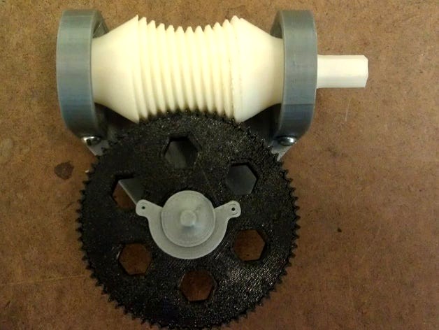
Worm gears find many uses in engineering applications due to their compact size and high gear reduction ratios. A disadvantage of this type of gear set is that only one tooth on the spur gear is engaged (or "in mesh") with the worm gear at any time. This causes high contact stresses which can accelerate wear.
This thing is a demonstration model of a hyperbolic (also known as an enveloping) worm gear. Both the worm gear and the spur gear teeth are cut from hyperbolic surfaces. This allows multiple teeth on the spur gear to engage the worm simultaneously. This reduces the contact stress between the gears, and allows higher torques to be transmitted through the gearset. A video showing the motion of the hyperbolic worm gears is shown here: http://youtu.be/O-MFFjBNCb8.
In this design 12 teeth on the spur are theoretically in constant mesh with the worm gear, although manufacturing tolerances result in less-than-perfect contact. The gear reduction is 72:1 (72 revolutions of the worm gear produce one revolution of the spur gear). Both the worm and spur are constructed using true involute gear tooth profiles. The worm gear is horizontally mounted on a pair of knife-edge bearings, and the spur is fastened to a vertical shaft using a c-clip.
This model makes an excellent hands-on demonstration of worm gears for a wide range of students. It can also be used as a challenge: computing and modeling the worm gear geometry is non-obvious. The solidworks files for the worm and spur have been attached for anyone interested.
Similar models
grabcad
free

Worm Gear
...ios and correspondingly high torque multiplication. they can also be used as speed reducers in low- to medium-speed applications.
3dwarehouse
free

Motorized Involute Spur Gears In Action Using SketchyPhysics 3.2
...ction and the addition of a sketchyphysics motor control. #gear #involute #motor #physics #reduction #sketchy #spur #teeth #tooth
grabcad
free

worm gear reducer
... of the worm on the worm wheel (or simply "the wheel"). they are typically comprised of a steel worm and a brass wheel.
grabcad
free

Worm Gear Assembly
... of the worm on the worm wheel (or simply "the wheel"). they are typically comprised of a steel worm and a brass wheel.
grabcad
free

Helical Gear
...st bearings, and a greater degree of sliding friction between the meshing teeth, often addressed with additives in the lubricant.
grabcad
free

12:1 Reduction Gearbox
...ur gear and 40 teeth spur gear.
stage 3 : 24 teeth spur gear and 48 teeth spur gear.
do share your views and connect on linkedin
grabcad
free

Helical Gear Wheel
... degree of sliding friction between the meshing teeth, often addressed with additives in the lubricant.
likes are appreciated...
grabcad
free

Spur Gear
...rial selection, backlash (clearance between teeth), lubrication, and load distribution should be carefully considered to ensure r
grabcad
free

Parametric Spur Gear (helical optionally)
...he "to mesh with" variable to the number of teeth on the gear that will mesh with it (providing it is the larger gear).
grabcad
free

#Bevel Gears
...d. straight bevel gear teeth actually have the same problem as straight spur gear teeth -- as each tooth engages, it impacts the…
Jsteuben
thingiverse
free

Channel lock pliers I modified for compression fittings by angrycannibal
...angrycannibal thingiverse just a quick and dirty modification to jsteuben#39;s 'adjustable groove-joint pliers'. i made the arms a bit...
thingiverse
free

DownLULA - A Poor Man's 9mm & .45 Loader/Unloader by MRLongus
...a 9mm &.45 magazine loader/unloader. it was remixed from jsteuben#39;s 9mm magazine speed-loader and greypoupon1532's 9mm & .45 thumb...
thingiverse
free

Greedy cup remix by everythingyoueverwant
...love the design of the greedy cup made by jsteuben but the outside of the cup seemed a bit...
thingiverse
free

Adjustable Groove-Joint Pliers by jsteuben
...thanks to the folks at 3dprint.com for writing a nice article about this thing! http://3dprint.com/55290/3d-printed-pliers-tools/
thingiverse
free

9mm SL mod for Taurus PT111-G2, CZ-75B, SIG p226 by Goodwynn89
...pt111-g2, cz-75b, sig p226 by goodwynn89 thingiverse i used jsteuben#39;s file and modified it to fit a taurus pt111g2...
thingiverse
free

ElectroMag-Test-Jig by MJHeed
...an electromagnet for a science fair project. so borrowing jsteuben#39;s worm gear (www.thingiverse.com/thing:343922) we assembled this test jig. changes...
thingiverse
free
Springfield XD 9MM Magazine Loader by Badkitty
...thingiverse this is a remix of the speed loader jsteuben created. i fine tuned the sizing to exactly fit...
thingiverse
free

Toolmaker's Vise by jsteuben
...cket-head cap screw, as well as a matching washer and hex nut, are required in addition to one copy of each of the printed parts.
thingiverse
free

"the Vise" (mini edition) by PRIma
...prima thingiverse remixed mini-version of the toolmaker`s vise by jsteuben my modifications: -downscaled to fit with m5 screw and...
Hyperbolic
3d_export
$99

Mouse 3D Model
...dent rig rigged cartoon funny anime humor humorous exaggerating exaggeration hyperbole people
mouse 3d model web3d 56722 3dexport
3d_export
$10

locus solus floor lamp
...irrational morphology of the eye of light meets the hyperbolic tubular steel giving life to a luminous flower with...
thingiverse
free

Non-Euclidean Chess Board (Wormhole) by DaveMakesStuff
...board: https://youtu.be/ufoccftpevw see here for a spherical board: https://www.thingiverse.com/thing:4643035 hyperbolic paraboloid board: https://www.thingiverse.com/thing:4647738 and "print in place" chess set:...
thingiverse
free

Non-Euclidean Chess Board (Hyperbolic Paraboloid) by DaveMakesStuff
...rd: https://www.thingiverse.com/thing:4655805
and "print in place" chess set: https://www.thingiverse.com/thing:4689389
thingiverse
free
Heptagonal Hyperbolic Tiling Coat Hook by dimnsionofsound
..., jackets, purses, and other articles for 6+ months now. just don't overload them with more than a 2-3 items on a single one.
thingiverse
free

Hyperbolic Triple by Graysmith75
...hyperbolic triple by graysmith75
thingiverse
triple blade 110mm diam fan.
hyperbolic leading and trailing edges with
thingiverse
free

Non-Euclidean Chess Board (Sphere) by DaveMakesStuff
...like the bare magnet look! see here for a hyperbolic paraboloid board: https://www.thingiverse.com/thing:4647738 wormhole board: https://www.thingiverse.com/thing:4655805 and "print in...
thingiverse
free

tree of whatever by davidatlas
...tree of whatever by davidatlas thingiverse grown hyperbolic ...
thingiverse
free
Angel/Demon Puzzle by ecoiras
...mosaic. in that design angels and demons tesselate the hyperbolic space. i reprojected the motif to planar euclidean space...
thingiverse
free

HE3D triple extruder (3in1out) vase (rotate line for hyperbolic curve) by he3d2016
...he3d triple extruder (3in1out) vase (rotate line for hyperbolic curve) by he3d2016
thingiverse
printed by 3in1out nozzle
Worm
3d_ocean
$3
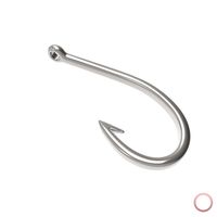
Fishing Hook
...mouth ocean outdoor plugs river saltwater sea sport water worm add more detail and realism to your projects with...
cg_studio
$49

Space Worm3d model
...es stylized cartoon proportions
.ztl .obj - space worm 3d model, royalty free license available, instant download after purchase.
3d_ocean
$16

After Lunch
...after lunch 3docean blood claw creature earth monster worm zbrsuh worm created in zbrush 4.0 3.176 mil 3dmax...
3d_ocean
$25

MW3DHDR0024 Autumn under the Trees
...sunny tree view mw3dhdr0024 autumn under the trees in worm / germany nice colorful leaves of trees in autumn...
3d_ocean
$25

MW3DHDR0023 Dom St. Peter Worms Germany
...s/germany a wonderful old gothic building interior. a kaiserdom build in the years 1130-1181. hight resolution hdri with tonem...
3d_ocean
$25
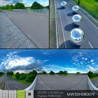
MW3DHDR0019 Bridge over the Highway
...panorama panoramic railing road roadway sky summer tree trees worm mw3dhdr0019 bridge over the highway a bridge passes over...
3d_ocean
$25

Bobbit worm
...dangerous horror insect millepede ocean predator scolopendra toxic worm
horrible creature with good subdivision friendly topology
3d_ocean
$5

20 Horror Pixel Texture Pack
...backgrounds. textures include: cobweb slime soil with bugs and worm bones x 2...
3d_ocean
$25

MW3DHDR0017 Rhine River Bridge Worms Gemany
...on late summerdays under the rhine river bridge in worms / germany. super hight resolution hdri with tonemapped background and...
3d_export
$10

Worm 3d Max Rigging 3D Model
...
worm rigg cartoon max
worm 3d max rigging 3d model download .c4d .max .obj .fbx .ma .lwo .3ds .3dm .stl deater07 105798 3dexport
Gears
3d_export
$99

Watch 9 3D Model
...skipper yh2wr4 clockwork watch gear wristwatch constantin swiss geneve gears mechanical isochronism parts chronograph exploded people watch 9 3d...
3d_ocean
$6

f-16 war plane
...f-16 war plane
3docean
f-16 f16 fly plane war war plane
no landing gear low poly ,
3d_ocean
$3

Gears 4
...nical parts process steampunk vehicle wheel work
10 different gear models volume 31-40 files: .3ds .c4d .obj note: you need vray
3d_ocean
$19

Samsung Gear VR innovator s6 edition
...smax, it includes a galaxy s6 edge phone model textures and uvs are included so you can custumize it in your favorite image ed...
3d_export
$49

Samsung Gear Fit Orange 3D Model
...king metrics hand
samsung gear fit orange 3d model download .c4d .max .obj .fbx .ma .lwo .3ds .3dm .stl humster3d 103801 3dexport
3d_export
$10

Gear 3D Model
...ism evolvent shaft wheel key
gear 3d model download .c4d .max .obj .fbx .ma .lwo .3ds .3dm .stl kazankindima20220 104036 3dexport
3d_export
$27
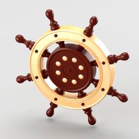
Decorative nautical helm 3D Model
...ive voyage journey
decorative nautical helm 3d model download .c4d .max .obj .fbx .ma .lwo .3ds .3dm .stl deanora 104141 3dexport
3d_export
$10

Wall Clock Gear Kare Design 3D Model
...3d model 3dexport clock kare karedesign watch metall arrow gears chromium chrome wall decor decoration flat home house loft...
3d_export
$49

Samsung Gear 2 Neo Charcoal Black 3D Model
... motion
samsung gear 2 neo charcoal black 3d model download .c4d .max .obj .fbx .ma .lwo .3ds .3dm .stl humster3d 104557 3dexport
3d_export
$849
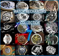
Watch mechanisms coll 7 3D Model
...7 3d model 3dexport clockwork watch gear wristwatch swiss gears mechanical isochronism parts chronograph people accessories collection value discount...