GrabCAD
Equ Drvn Gear With "Diametrical Pitch", "Number of Teeth" & "Pressure Angle" as User Input
by GrabCAD
Last crawled date: 1 year, 10 months ago
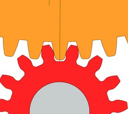
Equation Driven Involute Spur Gear Tooth Solidworks
This is one that has a TRUE involute tooth form driven by an equation.
USING:
"Diametrical Pitch" , "Number of Teeth" & "Pressure Angle" as User Input
It seems to be a stable template. It may “break” if an input value is beyond what it can calculate. BUT if it does break just change the value to something that is “in range” or a value that it can calculate. Perhaps the tip rad or the root rad is too big. Or the number of teeth too small. Or the Pressure angle is too large.
**************************************************************************
For the Large Gear:
Note: the template is set for the User input of the
following Global Variables in Solidworks:
"N"= 90 ---- Number of Teeth
"DP"= 15 ---- Diametrical Pitch
"PA"= 15 ---- Pressure Angle
"TipR"= .025'Tip Radus
"RootR"= .01'Root Radus
User can also change:
"a"= 1 / "DP" ---- addendum
"b"= 1.25 / "DP" ---- Dedendum
by changing the "1" or the "1.25"
The following are calculated:
"AngleA"= 360 / ( "N" * 2 ) ---- AngleA
"AngleB"= "AngleA" / 2 ---- AngleB
"PD"= "N" / "DP" ---- Pitch Diameter
"OD"= "PD" + ( 2 * "a" ) ---- Outside Diameter
"DR"= ( "PD" / 2 ) - "b" ---- Dedendum Radius
"AngleC"= "D2@SketchICL" ---- AngleC
Sketch Dimensions from Global Variables:
"ArcLen@SketchICL"= "TanLen@SketchICL"
"D1@CirPattern9"= "N" ---- Number of Teeth
"D1@Fillet1"= "TipR" ---- Tip Radus
"D1@Fillet2"= "RootR" ---- Root Radus
"D1@Fillet3"= "RootR" ---- Root Radus
The definition in the parameters of the parametric
“equation driven curve” for the involute form:
Xt = ("D1@SketchICL"/2) * (cos(t) + t*sin(t))
Xy = ("D1@SketchICL"/2) * (sin(t) - t*cos(t))
t1 = 0
t2 = 1
**************************************************************************
For the Small Gear:
Note: the template is set for the User input of the
following Global Variables in Solidworks:
"N"= 15 ----Number of Teeth
"DP"= 15 ---- Diametrical Pitch
"PA"= 15 ---- Pressure Angle
"TipR"= .005 ---- Tip Radus
"RootR"= .03 ---- Root Radus
"RootRAR"= .02 ---- Root Relief Angle Rad
"RootRA"= 10 ---- Root Relief Angle
User can also change:
"a"= 1 / "DP" ---- Addendum
"b"= 1.18 / "DP" ---- Dedendum
by changing the "1" or the "1.18"
The following are calculated:
"AngleA"= 360 / ( "N" * 2 ) ---- AngleA
"AngleB"= "AngleA" / 2 ---- AngleB
"PD"= "N" / "DP" ---- Pitch Diameter
"OD"= "PD" + ( 2 * "a" ) ---- Outside Diameter
"DR"= ( "PD" / 2 ) - "b" ---- Dedendum Radius
"AngleC"= "D2@SketchICL" ---- AngleC
Sketch Dimensions from Global Variables:
"ArcLen@SketchICL"= "TanLen@SketchICL"
"D1@CirPattern1"="N" --- Number of Teeth
"D1@Fillet1"= "TipR" ---- Tip Radus
"D1@Fillet2"= "RootR" ---- Root Radus
"D2@SketchICLE"="DR" ---- Dedendum Radius
"D3@Sketch2"="DR" ---- Dedendum Radius
"D1@Sketch2"="RootRAR" ---- Root Relief Angle Rad
"D2@Sketch2"="RootRA" ---- Root Relief Angle
"D4@Sketch2"="RootRA" ---- Root Relief Angle
The definition in the parameters of the parametric
“equation driven curve” for the involute form:
Xt = ("D1@SketchICL"/2) * (cos(t) + t*sin(t))
Xy = ("D1@SketchICL"/2) * (sin(t) - t*cos(t))
t1 = 0
t2 = 1
**************************************************************************
Note: The Small Gear has in it the global variables:
"Root Relief Angle Rad" and "Root Relief Angle"
This is so when a Small Gear (pinion) is mated with a
Large Gear there will be clearance. (adjust values as required)
Similar models
grabcad
free

Equation Driven Involute Curve Spur Gear Tooth Form in Solidworks
...the diametrical pitch and number of teeth to determine the pitch diameter --- "pd"= "n" / "dp"
grabcad
free

Equation Driven Involute Spur Gear W/ Approximated Involute Profile - Video 2
...ction. this was made from a video on creating involute spur gears. see video here:
https://www.youtube.com/watch?v=l1kuu8oy7mu
grabcad
free

Involute Spur Gear (Equation Updating) and Design Guide
...d. this was made from a video on involute spur gear design. please see video here:
https://www.youtube.com/watch?v=rsf_pvy5sva
grabcad
free

Ryan's Herringbone Gear Template
...n is based on a user-defined diametrical pitch, number of teeth, pressure angle, gear width and helix angle (typically 15 - 45°).
grabcad
free

Equation Driven Involute Gear in SOLIDWORKS
...r set the following parameters:
- number of teeth (n)
- dimetral pitch (p)
- pressure angle (a)
- hole diameter (dh)
- length (l)
grabcad
free

Inch Parametric Involute Spline Gear Set - SW 2015 EDU
...gn the base of the spline on base circle directly. the spline location is currently set with a coincident mate on the tooth width
grabcad
free

involute spur gear
...le= 20deg
pitch circle radius= 9mm
number of teeth= 12
module= 1.5
gear profile drawn using equation driven curve of an involute
thingiverse
free

Simple Gear Example-Inkscape to Openscad by mizliz
...e(cd)
pitch diameter(d)
number of teeth(n) & diametrical pitch(p)
cd=(d1+d2)/2cd=(n1+n2)/2p
grabcad
free

Request: Bevel Gear/Pinion 31.75 Diametral Pitch
...ular
ø 20.0000 deg pressure angle
ø 92.0000 deg shaft angle
mg 0.4500 ratio, 1:x
pinion number of teeth 9
gear number of teeth 20
grabcad
free

Sprocket and Bevel Gear Generators
...l_gear_process.pdf
https://www.youtube.com/watch?v=nwwi_wdgctu
https://www.daycounter.com/calculators/bevel-gear-calculator.phtml
Equ
turbosquid
$35

Mato grosso (Hyphessobrycon eques)
...osquid
royalty free 3d model mato grosso for download as max on turbosquid: 3d models for games, architecture, videos. (1406509)
thingiverse
free

Case for Board Arduino Nano + Shield Internet by chpatiss
...d9 for synchrone serial) with 7 optocouplers 4n25 or equ (6 for input ,1 for output).all pul-up resistors could...
thingiverse
free

Urticine-O by camoncada
...an amazing functional sculpture inspired by a coral named urtinice-equs. this coral takes part of the most beautiful family...
3dbaza
$4

Decor Set 60 (82671)
...5 rhino statue<br>- bungalow 5 hanya statue<br>- bungalow 5 equ statue<br>- bungalow 5 henri large statue<br>- bungalow 5 demi...
grabcad
free

LMS2430, SOLAR CHARGE CONTROLLER
...and natural air cooling - 4-stage charge period management (equ bulk, abs, float) - charging temperature compensation function -...
cg_trader
$125
Leafy sea dragon
...leafy sea dragon cg trader phycodurus equs model, known as leafy sea dragon. the model is...
cg_trader
$44

Office Building 3D model
...and viewport aren't so heavy. trees, plants and office equ set mesh are separeted as single mesh in different...
cg_trader
$30

Office Building 3D model
...and viewport aren't so heavy. trees, plants and office equ set mesh are separeted as single mesh in different...
cg_trader
$52

Phycodurus eques seadragon
...phycodurus eques seadragon
cg trader
notice:
cg_trader
$7

Knight armor R
...to the greek hippeis and hoplite (ἱππεῖς) and roman equs and centurion of classical antiquity.[3] in the early middle...
Diametrical
3ddd
$1

Светильник de Majo / Micos Lightdrops system
...
de majo
de majo
micos lightdrops system
diametr 60 cm
hight max 2000 cm
3x8.7w 240vac /2300lm
led 3000 k
warm white
max 15 glass
3ddd
$1
Светильник de Majo / Charlotte Lightdrops system
...majo
de majo
charlotte lightdrops system
diametr 60 cm
hight max 2000 cm
3x8.7w 240vac /2300lm
led 3000 k
warm white
max 15 glass
3ddd
$1
Светильник (VANAMO PENDANT)
...mm
diametr- 150mm; 100mm; 80mm; 50mm; 60mm;
материал плафонов -прозрачное и матовое градиентное стекло.
приятного пользования!
3ddd
free

Часы Misendemeure Village
...
clock villagehttp://www.misendemeure.com/en/collection/decorative-object/decorative-clock/pendule-de-village
3ddd
$1
Консоль Liberty custom
... консоль
консоль liberty custom
производитель: heijden hume
параметры:hight 95/diametr 45
отделка: дуб/лакированный верх
3d_export
$5
Wheel toy - D1W2
...d printing. multiformat: igs; obj; stl; x_t; x_b; bip super price for first time buyers! see 3d presentation in free attachments.
3d_export
$5

Wheel toy - 2005
...3d games to 3d printing. multiformat: igs; obj; stl; step; x_t; x_b; dwg; dwfx; fbx; bip; zpr, super price for first time buyers!
3d_export
$5

realistic bar chair blue-black
... seat diametr 32 cm baked texture atlases: diffuse roughness normal type files textures .png the size 4096*4096 archive file zip.
3d_export
$5

realistic bar chair brown-black
... seat diametr 32 cm baked texture atlases: diffuse roughness normal type files textures .png the size 4096*4096 archive file zip.
3d_export
$5

bar chairs chrome and graphite
... seat diametr 32 cm baked texture atlases: diffuse roughness normal type files textures .png the size 4096*4096 archive file zip.
Input
3ddd
$1
Miniforms Olivia
...cm functional and eect, perfect not only for the input it lends itself to solve taste dierent situations. the...
3d_ocean
$5

Apple Magic Mouse
...apple magic mouse 3docean apple bluetooth imac input ios macintosh magic mouse mouse osx power mac touch...
archive3d
free
Input 3D Model
...telephone input
telephone input n030708 - 3d model (*.gsm+*.3ds) for interior 3d visualization.
cg_studio
$59

Wacom Bamboo Fun A53d model
...fun a53d model cgstudio electronics wacom bamboo fun tablet input pen mouse paint draw a5 medium intuos cintiq .max...
archibase_planet
free
Keyboard
...keyboard archibase planet input keyboard keyboard office equipment pro keyboard - 3d model...
cg_studio
$29

FSC Media Remote Control3d model
...fujitsu siemens computers pc hardware accessories component perhiperal keyboard input remote ">control .max - fsc media remote control 3d...
cg_studio
$29
Wacom Bamboo Fun Mouse3d model
...bamboo fun mouse3d model cgstudio electronics wacom bamboo fun input mouse paint draw intuos cintiq .max .3ds .lwo .obj...
3d_export
$15

UltraFlat Keyboard 3D Model
...ultraflat keyboard 3d model 3dexport keyboard desktop input office computer pc cpu interface logitech usb ultraflat keyboard...
3d_export
$13

Wacom Bamboo 3D Model
...wacom bamboo 3d model 3dexport wacom bamboo fun tablet input device pen mouse paint draw stylus computer drawing materials...
3d_export
$60

Fender BassMan Amp 3D Model
...guitar sound scene amp concert rock power equipment effects input plug cable music fender bassman amp 3d model rendersteel...
Pitch
3d_ocean
$19
Multi sport court centrum pack
...basketball bench chair crowd football game goal match olympic pitch player soccer stadium team tennis tribune volleyball medium detailed...
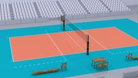
3d_export
$33

Multi sport court centrum pack 3D Model
...olympic basketball volleyball soccer football tribune goal game crowd pitch player team match bench multi sport court centrum pack...
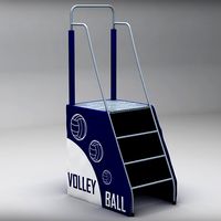
cg_studio
$6
Referee stand volleyball low poly3d model
...beach ball referee jury outdoor football tennis court hall pitch .max .fbx .3ds .obj - referee stand volleyball low...
cg_studio
$35

Baseball stadium pitch diamond low poly3d model
...bx .3ds .obj - baseball stadium pitch diamond low poly 3d model, royalty free license available, instant download after purchase.
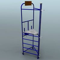
3d_ocean
$7
Referee stand
...ball beach chair court football hall judge jury outdoor pitch referee sport stadium tennis volleyball medium detailed 3d model...
3d_ocean
$6

Pack Snapback 3D Model
...gear hat headgear hip hobby hop max model pitch pitchr rap snapback softball sports strike pack snapback 3d model...
3d_ocean
$7
Judge stand
...ball beach chair court football hall judge jury outdoor pitch referee sport stadium tennis volleyball medium detailed 3d model...
3d_export
$99
Volleyball court - real size 3D Model
...- real size 3d model 3dexport volleyball court ball pitch hall sports sport competition winner player real size full...
3d_ocean
$3
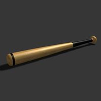
Baseball Bat
...3docean america ball baseball bat children equipment game league pitch play sport team wood baseball bat modelled in 3ds...
3d_ocean
$9
Tennis court bench chair
...center centre champion field game grand match olympic open pitch player racket set slam sport stadium tennis tribune umpire...
Teeth
3d_export
$29

MuscularMohit 3D Model
...3d model 3dexport model cartoon film movies hair texture teeth eye skin real man muscular male boy leather clothey...
3d_export
$29

Sexy Girl Malvika 3D Model
...3dexport model people charactor human person cartoon hair texture teeth eye skin real leady women girl sexy female clothey...
3d_export
$29
Sexy Female Champa 3D Model
...3dexport model people charactor human person cartoon hair texture teeth black eye skin real leady women girl sexy female...
3d_export
$20

Human Skeleton 3D Model
...3d model 3dexport human skeleton bon hand legs head teeth ghost denger white cream poly real fancy fantasy human...
3d_ocean
$5

ELEGANT SCULL 3D MODEL
...jaw lines male medical pirate scientific skeletal skeleton skull teeth zombie elegant scull 3d model .obj and .3ds...
3d_ocean
$16
3D Baby
...poly model. it has full body texture and also teeth & toung. it has basic rigging. it will easy...
3d_ocean
$29

Security 3D
...medical muscular pant people person realistic shoes t shirt teeth texture torso young high-quality security model that is ready...
3d_export
$75

Low Poly Realistic Elephant 3D Model
...max maya african nature tusk safari realistic detailed hathi teeth low poly realistic elephant 3d model download .c4d .max...
3d_export
$15
Toothpick Holder 3D Model
...toothpick holder 3d model 3dexport toothpick wood teeth detritus dental hygiene cocktail stick wooden bamboo clean oral...
cg_studio
$45
Human skeleton3d model
...skeletal system human skeleton bones bone spine skull femur teeth skeleton system .obj .mb .max .ma .fbx .dae -...
Pressure
3d_export
$5
Montana Paint Spray Can 3D Model
...can spray paint graffiti cap model aerosol freon ozone pressure container mtn art montana paint spray can 3d model...
3ddd
$1
Henry Pressure Balance Control Valve Trim
...henry pressure balance control valve trim
3ddd
waterwarks
henry pressure balance control valve trim
3ddd
$1
Набор картин и декоров для стен
...металлических пластин; - пара картин "right and left hand pressure points gold leaf " в рамках из дерева цвета...
3ddd
$1
Duravit Mirrorwall MW 9834
...duravit http://www.duravit.com/website/homepage/products/product_overview/series/mirrorwall.com-en.html/p-108955 mirrorwall mirrorwall 4 mirror doors (below including pressure lock), 1 double mirror door including 12 detachable wooden...
3ddd
$1
Elba
...garden table (for in and outdoor use), white high pressure laminate with black inner core/matt black structure...
3d_ocean
$15
Steam iron
...iron 3docean bosch cloth electrolux flat houseware iron ironing pressure product samsung siemens steam steam iron steam irons tefal...
3d_ocean
$12
oxygen cylinder
...grey isolated lab life metallic nautical object ocean oxygen pressure recreational regulator research science silver steel tank valve 3d...
3d_ocean
$6
lighter
...lighter
3docean
flame flammable fluid gas lighter liquid metal plastic pressurized
lighter texture map included.
3d_ocean
$25
Mine Control Room : A1
...control room dial gauge joystick lever mine nuclear office pressure science originally modeled for a mine, this is the...
3d_ocean
$5
Moka Pot- Coffe Maker
...food home house italian java low poly machine maker pressure robusta stove top 3d moka...
Angle
3d_export
$26
Goniometer 3D Model
...goniometer 3d model 3dexport goniometer angle measure drawing tool goniometer 3d model tartino 65342...
3ddd
$1
Floor Angle Lamp
...floor angle lamp
3ddd
workroom
floor angle lamp by workroom
400 mm w x 1550 mm h
3d_export
$25
Floor lamp Fabbian F05C0102 Angle 3D Model
...photo
floor lamp fabbian f05c0102 angle 3d model download .c4d .max .obj .fbx .ma .lwo .3ds .3dm .stl jockermax44 103208 3dexport
3ddd
$1

Fiji Palm
...not used for tamu that they are with sharp angle and everything else is flattened...
3ddd
$1
1955 angle poise lamp
...
настольная лампа
produit interieur brut
1955 angle-poise lamp
размеры: 120x165x800(h)
сайт:http://www.pib-home.co.uk/
archive3d
free

Hooks 3D Model
...hooks 3d model archive3d hooks hook angle fish-hook bait hooks - 3d model (*.gsm+*.3ds) for interior...
3ddd
$1

Jo Stool by Punt
...of j-shaped moulded wood cut at a 30 degree angle the hermetic structure and the j-shaped legs, guarantee a...
3ddd
$1
Irving Bed by Modloft
...by modloft. it's simple yet sophisticated style bed, softly angle polished flat steel legs contrast with luxurious novatex upholstery....
3ddd
$1

Двуспальная кровать Angle
...ngle. двуспальную кровать с подъемным механизмом angle оценят и те, кто любит практичность: кровать имеет объемый ящик для белья.
3ddd
$1

Kursi Leather Chair
...leather chair 3ddd puji hand crafted with gorgeous soft angle and a low seat, this is the perfect chair...
Gear
3d_export
$99

Watch 9 3D Model
...skipper yh2wr4 clockwork watch gear wristwatch constantin swiss geneve gear mechanical isochronism parts chronograph exploded people watch 9 3d...
3d_ocean
$6
f-16 war plane
...f-16 f16 fly plane war war plane no landing gear low poly...
3d_ocean
$3

Gears 4
...nical parts process steampunk vehicle wheel work
10 different gear models volume 31-40 files: .3ds .c4d .obj note: you need vray
3d_ocean
$19

Samsung Gear VR innovator s6 edition
...smax, it includes a galaxy s6 edge phone model textures and uvs are included so you can custumize it in your favorite image ed...
3d_export
$49

Samsung Gear Fit Orange 3D Model
...king metrics hand
samsung gear fit orange 3d model download .c4d .max .obj .fbx .ma .lwo .3ds .3dm .stl humster3d 103801 3dexport
3d_export
$10
Gear 3D Model
...ism evolvent shaft wheel key
gear 3d model download .c4d .max .obj .fbx .ma .lwo .3ds .3dm .stl kazankindima20220 104036 3dexport
3d_export
$27
Decorative nautical helm 3D Model
...helm decorative nautical steering wheel ship fleet sea rudder gear tiller captain navigation navigate sail skipper drive voyage journey...
3d_export
$10

Wall Clock Gear Kare Design 3D Model
...oft design
wall clock gear kare design 3d model download .c4d .max .obj .fbx .ma .lwo .3ds .3dm .stl valeriya9103 113577 3dexport
3d_export
$49

Samsung Gear 2 Neo Charcoal Black 3D Model
... motion
samsung gear 2 neo charcoal black 3d model download .c4d .max .obj .fbx .ma .lwo .3ds .3dm .stl humster3d 104557 3dexport
3d_export
$849
Watch mechanisms coll 7 3D Model
...7 3d model 3dexport clockwork watch gear wristwatch swiss gear mechanical isochronism parts chronograph people accessories collection value discount...
Number
3d_export
$16

Puzzle Modern Wall Clock 3D Model
...wall design decoration max vray puzzle shape photo photograph number puzzle modern wall clock 3d model trinity23 32765...
3ddd
$1
BESTÅ system Combinations with pictures
...с ящиками, черно-коричневый, selsviken глянцевый/коричневый размер: 120x40x74 см article number 590.896.08 ящики и дверцы закрываются мягко и бесшумно, благодаря...
3ddd
$1
Currey & Company Balthazar
...balthazar ceiling mount dimensions: 21h x 18d x 18w number of lights: 3 shades: chandelier not suitable for shades...
3ddd
$1

Dresser Romantic Cirrus Big
...x 0.85 x 0.55 meters weight: 52.95 kg product number ...
3ddd
$1
Basket Rope Round
...x 0.46 x 0.46 meters weight: 5 kg product number 37077 для крупных планов включите сглаживание. p,s, плед идет...
3ddd
$1

Currey & Company Orion
...product name: orion chandelier, large dimensions: 37h x 34rd number of lights: 12 shades: refer to catalog pages 280-281...
3d_ocean
$5

Billard Balls
...billiard ball pack contains 16 low poly billiard balls. numberng from 1 to 15 plus the cue ball. each...
3d_ocean
$15

Fridge
...of the refrigerator and cans of coca cola. the number of polygons of the refrigerator – 4 213. polygons...
3d_ocean
$12

Classic Guitar
...633384 polygons: 615484 -created in cinema 4d studio r14 -number of main files: 3 (.c4d, .obj,...
3d_ocean
$7

Pirates Globe
...low poly 3d model of a pirate globe: • number of polygons – 915 • number of vertices –...
User
3ddd
$1

Картина в раме: 20 шт (сборник 49) Морская тема
...все имена на латинице, без пробелов остальные сборники картин здесь:http://3ddd.ru/user/flamenezo ...
3ddd
$1
Картина в раме: сборник 45. Морская тема
...все имена на латинице, без пробелов остальные сборники картин здесь:http://3ddd.ru/user/flamenezo ...
3ddd
$1
Картина в раме: 14 шт (сборник 34) Морская тема
...max, fbx, mat, текстуры масштаб: мм остальные сборники картин здесь:http://3ddd.ru/user/flamenezo ...
3ddd
$1
Картина в раме: 9 шт (сборник 29) Абстракция
...max, fbx, mat, текстуры масштаб: мм остальные сборники картин здесь:http://3ddd.ru/user/flamenezo ...
3ddd
$1

Dining Chair 8562-151, River Run, Schnadig
...obj - прилагается библиотека материалов. - здесь другие мои модели:http://3dsky.org/user/jekson777/models http://3ddd.ru/users/jekson777/model ...
3ddd
$1
Настенное зеркало (Сборник №3)
...5) зеркало круглое handmade "шато" авторы:http://www.livemaster.ru/decorativeglass http://www.livemaster.ru/zakutin http://www.livemaster.ru/son4oys остальные сборники зеркал здесь:http://3ddd.ru/user/flamenezo ...
3d_ocean
$1
Stained Glass Window Decal
...512×512 also check out my other works on envato http://audiojungle.net/user... ...
3d_ocean
$1
Seamless Hand Painted Rough Rocks Texture
...1024×1024 also check out my other works on envato http://audiojungle.net/usernkovac/portfo... ...
3d_ocean
$2

Seamless Hand Painted Stone Wall 2
...1024×1024 also check out my other works on envato http://audiojungle.net/usernkovac/portfo... ...
3ddd
$1
RH/ VINTAGE BASEBALL STRIPE DRAPERY PANEL
...материалы имеют индивидуальное имя на английском языке. другие мои моделиhttp://3ddd.ru/user/scion/models быстрых...