Thingiverse
7 turn Helical FPV antenna (5.8 GHz) by Dvogonen
by Thingiverse
Last crawled date: 3 years ago
I made a 5 turn helical antenna a while back that has been fairly popular. The original antenna is found here; http://www.thingiverse.com/thing:858112
Since then I have gotten several requests for a longer 7 turned version, so I thought I would take a stab at it. The older antenna was a remix of another design, but the new one is made from scratch.
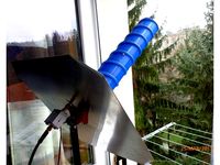
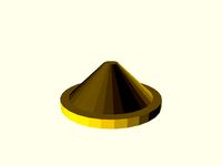
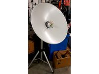
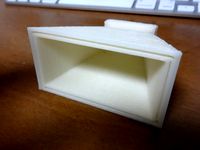
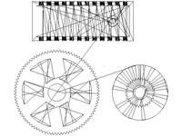
I have wondered why the base reflector of helical antennas are one wavelength in diameter. Would a wider base make any difference? A while back I found Serbian university research papers that described practical tests conducted with different reflector designs for helical antennas. It turned out that a bowl reflector with a 2.5 wavelength diameter is vastly superior to the standard 1 wavelength disc. I have designed such a reflector. If you decide to use it, you could attach aluminium or copper foil to the surface, or use the design as a template for a reflector in copper or brass mesh.
There are further papers that suggests use of a cylindrical reflector. It seems promising, since it would be easy to realize in many materials, but I have not made any design for it:http://home.etf.rs/~milanilic/publications/papers/AWPL-2006_01624449.pdfhttp://home.etf.rs/~milanilic/publications/papers/Olcan-Eucap06.pdf
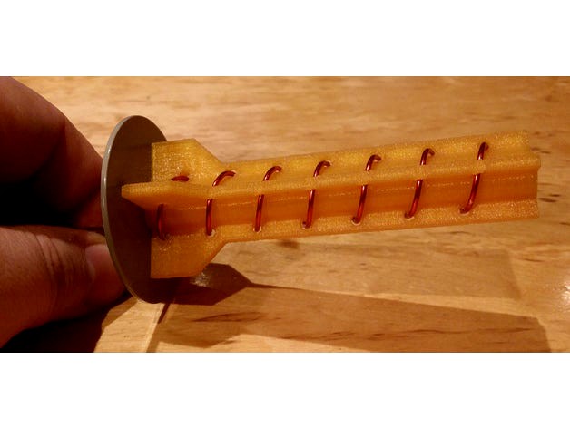
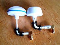
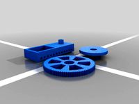
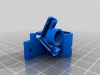
The design criteria are the same as for the 5-turn version: I wanted an antenna that offered full protection for the wire, was compact and easy to print and did not require using glue for assembly. My design consists of two items that are held together with a single screw. It can simply not get any simpler.
There are both left and right hand polarized versions of the former and the wire holder. Make sure to print the version you need.
Build Instructions
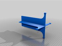
The reflectors should be seen mainly as templates. Print one and use it to produce a reflector out of PCB material or copper. If you use a PCB, the copper surface must be turned forward, i.e. be the side that the wire holder is mounted to.
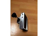
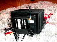
Insert the antenna connector in the out-most hole of the reflector and cut the wire 5-6 mm above the surface.
Fan out the outer isolation of the antenna wire and solder it to the reflector. There is a picture of this step in the process to make it easy to see what I mean.
Paint or lacquer the reflector to make it fingerprint proof. This step is purely aesthetic and may be skipped.
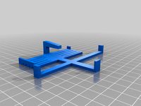
Print the holder and the former.
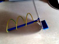
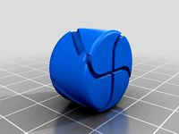
Use the wire former to create a wire spiral.
Thread the wire on the holder and cut it to length in place.
Use an M3 screw and nut to fasten the holder to the reflector.
The last step is soldering the main wire and the antenna center wire together. To achieve the best results possible the connection to the antenna wire is very important. The main wire should be in parallel with the reflector board for the last 4 mm of it´s length. This section of the wire should be located 2 mm from the surface of the reflector (thanks to Dave855 for the information)
Since then I have gotten several requests for a longer 7 turned version, so I thought I would take a stab at it. The older antenna was a remix of another design, but the new one is made from scratch.
I have wondered why the base reflector of helical antennas are one wavelength in diameter. Would a wider base make any difference? A while back I found Serbian university research papers that described practical tests conducted with different reflector designs for helical antennas. It turned out that a bowl reflector with a 2.5 wavelength diameter is vastly superior to the standard 1 wavelength disc. I have designed such a reflector. If you decide to use it, you could attach aluminium or copper foil to the surface, or use the design as a template for a reflector in copper or brass mesh.
There are further papers that suggests use of a cylindrical reflector. It seems promising, since it would be easy to realize in many materials, but I have not made any design for it:http://home.etf.rs/~milanilic/publications/papers/AWPL-2006_01624449.pdfhttp://home.etf.rs/~milanilic/publications/papers/Olcan-Eucap06.pdf
The design criteria are the same as for the 5-turn version: I wanted an antenna that offered full protection for the wire, was compact and easy to print and did not require using glue for assembly. My design consists of two items that are held together with a single screw. It can simply not get any simpler.
There are both left and right hand polarized versions of the former and the wire holder. Make sure to print the version you need.
Build Instructions
The reflectors should be seen mainly as templates. Print one and use it to produce a reflector out of PCB material or copper. If you use a PCB, the copper surface must be turned forward, i.e. be the side that the wire holder is mounted to.
Insert the antenna connector in the out-most hole of the reflector and cut the wire 5-6 mm above the surface.
Fan out the outer isolation of the antenna wire and solder it to the reflector. There is a picture of this step in the process to make it easy to see what I mean.
Paint or lacquer the reflector to make it fingerprint proof. This step is purely aesthetic and may be skipped.
Print the holder and the former.
Use the wire former to create a wire spiral.
Thread the wire on the holder and cut it to length in place.
Use an M3 screw and nut to fasten the holder to the reflector.
The last step is soldering the main wire and the antenna center wire together. To achieve the best results possible the connection to the antenna wire is very important. The main wire should be in parallel with the reflector board for the last 4 mm of it´s length. This section of the wire should be located 2 mm from the surface of the reflector (thanks to Dave855 for the information)
Similar models
thingiverse
free

5 turn Helical FPV antenna (5.8 GHz) by Dvogonen
...length. this section of the wire should be located 2 mm from the surface of the reflector (thanks to dave855 for the information)
grabcad
free

5.8GHz helical antenna RHCP
...wooden stick. and a 52 mm pcb board reflector.
can be printed at shapeways.
https://www.shapeways.com/shops/farmer_goes_airborn
thingiverse
free
4 turn helical antenna for 1280mhz and 1405mhz by HenrikJaderstrom
...oles are for 1405mhz and outer holes are for 1280mhz.
use 1.3mm solid copper wire and a fr4 circute board blank for the reflector
thingiverse
free

5.8 GHz Helical Antenna by FrankenberryPi
...t hand circularly polarized antenna. it won't work if your transmitter is lhcp. used this with success on fatshark goggles.
thingiverse
free
Helical antenna for Inmarsat by Die_Bastelkammer
...ound at uhf-satcom.com.
the upgrade i made are the mountings for the antenna itself and the helical wire part onto the reflector.
thingiverse
free

Customizable Helix (Helical) Antenna Frame and Winding Template by stylesuxx
... the wave trap and made the helix antenna popular for fpv.
references
rcgroups' ibcracy helical antenna and wavetrap tutorial
thingiverse
free

5.8g 7 turn helical antenna former by FalconRad
...8g 7 turn helical antenna former by falconrad
thingiverse
use this to form the initial shap of your 7 turn 5.8g helical antenna.
thingiverse
free
Helix antenna for Outernet by Way
...a-design-calculator.phtml
edit:
this antenna is designed for 1545.525 mhz - check if outernet is still working on this frequency.
thingiverse
free

GBHelicalAntenna v1 - FPV 5.8 GHz 5 turn helical antenna by gebeclair
... wire and apply a varish coating after assembly to prevent corrosion.
the design is rhcp polorized, but a symetry will give lhcp.
thingiverse
free
S helical 5.8ghz by runaway380
...this is a 5.8ghz antenna for the rg402 coax similar to a helical antenna. this should be printed in...
Dvogonen
thingiverse
free
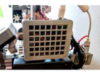
Cover for MKS Base printer board by Dvogonen
...mks base printer board by dvogonen
thingiverse
a simple cover for mks base printer controller boards.
the cover snaps behind the
thingiverse
free
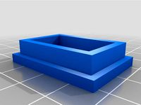
Square device foot by Dvogonen
...o speakers. this provides good vibration isolation.
i will publish a few other customizable device foot designs with other forms.
thingiverse
free
Circular device foot by Dvogonen
...o speakers. this provides good vibration isolation.
i will publish a few other customizable device foot designs with other forms.
thingiverse
free
Spiked device foot by Dvogonen
...o speakers. this provides good vibration isolation.
i will publish a few other customizable device foot designs with other forms.
thingiverse
free

Ingen Reklam Tack! by Dvogonen
...able.
created in freecad. the design file is posted together with the printable stl file, for those who want to tweak the design.
thingiverse
free
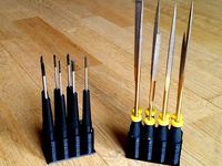
Customizable Screwdriver Holder by Dvogonen
...d it quite convenient to store my screwdrivers as a package. i use a rubber band to keep the two parts together while in storage.
thingiverse
free
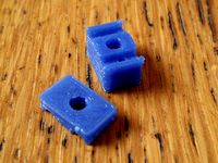
Piezo buzzer holder by Dvogonen
...possible to mount a piezo buzzer with a single m3 screw.
print with reasonable resolution (0.2) since the outer walls are thin.
thingiverse
free
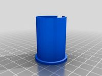
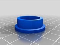
Customizable Tube Collar by Dvogonen
...ade a customizable version. just enter the desired height etc in the customizer to create your own collar for your specific need.
thingiverse
free
FPV antenna bend by Dvogonen
... matches the thickness of your coaxial wire, insert the wire and then clamp it down using two small zip ties. problem solved.
.
thingiverse
free

Customizable screwdriver stand (top part) by Dvogonen
...bber band. in this way you can store your precision screw drivers as a convenient package and have them ready for use in seconds.
Ghz
3d_export
$60

HTC Sensation Pyramid 3D Model
...htc sensation pyramid 3d model 3dexport htc 12 ghz dual core unibody 4g wildfire evo desire hd incredible...
3ddd
$1
Варочная поверхность ILVE MOD.H60CNV BRILLIANT CUPPER
...объектов примероное время render - core 2 duo 2.1 ghz /2gb - frame 2400x1800 - 2:33 min рекомендую в...
thingiverse
free

Septum-Feed-10-Ghz by IKOEQJ
...septum-feed-10-ghz by ikoeqj
thingiverse
feed 10 ghz eme.
thingiverse
free
1.3 ghz vtx mount
...1.3 ghz vtx mount
thingiverse
a mount designed to fit in the side saddle of the full size drak. will hold a fullsize 1.3 ghz
thingiverse
free

5.8 GHz Cloverleaf Protection Dome by SnakeP
...5.8 ghz cloverleaf protection dome by snakep
thingiverse
protection dome / protection cover for 5.8 ghz cloverleaf antennas
thingiverse
free
2.4 GHz Helical Antenna (RHCP) by Luc_69
...4 ghz helical antenna (rhcp) by luc_69
thingiverse
2.4 ghz helix antenna (rhcp) for cassgrain dish or direct use without a dish.
thingiverse
free

5.8 ghz antenna cover by kuiko
...5.8 ghz antenna cover by kuiko
thingiverse
5.8ghz antenna cover
thingiverse
free

Caja VRX Matek 1,2/1,3 GHz by piticho
... matek 1,2/1,3 ghz by piticho
thingiverse
caja a medida para alojar un receptor matek 1,2/1,3 ghz y que esté protegido de golpes
thingiverse
free
Microwave (8 to 12 GHz) horn antenna by kodera2t
...odera2t
thingiverse
microwave (8 to 12 ghz) horn antenna with wr-90 interface. actual use needs conductive paint on abs surface.
thingiverse
free
Antennenschutz 5,8 GHz Immerson by Chris999998
... immerson by chris999998
thingiverse
the lower part should be printed with supporting material
setting for support material 20%
Helical
3d_export
$5
helical gear
...helical gear
3dexport
helical gear
3d_export
$5
Helical Gear
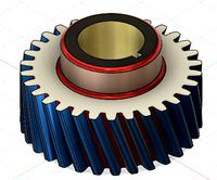
...l contact ratio which can improve vibration and noise. badly designed helical gears can be noisier than well designed spur gears.
turbosquid
$5
Helical Gear
...squid
royalty free 3d model helical gear for download as stl on turbosquid: 3d models for games, architecture, videos. (1502723)
turbosquid
$4

helical gears
...id
royalty free 3d model helical gears for download as blend on turbosquid: 3d models for games, architecture, videos. (1423917)
turbosquid
$40

Helical Stairs
...el helical stairs for download as 3ds, max, ige, obj, and fbx on turbosquid: 3d models for games, architecture, videos. (1422987)
turbosquid
$32

armchair-Helical
... available on turbo squid, the world's leading provider of digital 3d models for visualization, films, television, and games.
turbosquid
$20

helical gear
... available on turbo squid, the world's leading provider of digital 3d models for visualization, films, television, and games.
turbosquid
$10

helical gear
...cal gear for download as max, unitypackage, 3ds, fbx, and obj on turbosquid: 3d models for games, architecture, videos. (1667275)
turbosquid
$4

Helical gear
... gear for download as sldpr, 3dm, 3ds, fbx, ige, obj, and stl on turbosquid: 3d models for games, architecture, videos. (1530622)
3d_export
$50

HELICAL BEVEL GEAR
...lel and perpendicular. in parallel-axis helical gears the two opposite-hand gears provide quiet operation and high load capacity.
Fpv
turbosquid
$1

FPV VTX Antenna
...e 3d model fpv vtx antenna for download as obj, fbx, and stl on turbosquid: 3d models for games, architecture, videos. (1230317)
3d_export
$9

Fpv logo 3D Model
...onogram vehicle part of auto transport 3d model logo emblem detailed high quality badge
fpv logo 3d model rmodeler 59628 3dexport
3d_export
$8
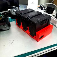
dji fpv battery slot holder
...er for 3 dji fpv batteries. holds perfectly without shaking. need 1 m3 countersunk head bolt. need to print 6 pin, 1 case, 1 cap.
3d_export
$10
fpv camera hd 700tvl
...aterials are logically named<br>the main format is in 3ds max 2009.<br>satisfcation garranteed..<br>thank you !
thingiverse
free
FpV Mount (SOPORTE FPV) by elborjas1987
...fpv mount (soporte fpv) by elborjas1987
thingiverse
this is a fpv mount with the same holes of naza base.
thingiverse
free
fpv by tbutera
...fpv by tbutera
thingiverse
fpv
thingiverse
free
fpv by tbutera
...fpv by tbutera
thingiverse
fpv
thingiverse
free
FPV DRONE ROOSTER DJI FPV PART
...fpv drone rooster dji fpv part
thingiverse
fpv drone rooster dji fpv install part
thingiverse
free
FPV monitor
...tml?rmmds=myorder&cur_warehouse=cn
link for download : https://cults3d.com/fr/mod%c3%a8le-3d/divers/fpv-monitor-ecran-fpv-faf
thingiverse
free
FPV receiver mount for FPV display by petrex
...eceiver mount for fpv display by petrex
thingiverse
aomway receiver mount for field view 777 fpv monitor. with small cable tray.
Antenna
archibase_planet
free
Antenna
...chibase planet
antenna aerial television antenna
antenna kathrein n090913 - 3d model (*.gsm+*.3ds) for exterior 3d visualization.
archibase_planet
free
Antenna
...antenna
archibase planet
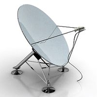
satellite antenna
antenna 1 - 3d model (*.gsm+*.3ds) for exterior 3d visualization.
archibase_planet
free
Antenna
...antenna
archibase planet
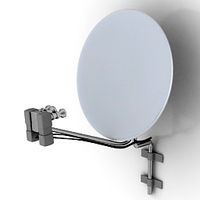
equipment satellite antenna
antenna 2 - 3d model (*.gsm+*.3ds) for exterior 3d visualization.
archibase_planet
free
Antenna
...ntenna
archibase planet
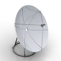
satellite antenna equipment dish aerial
antenna 3 - 3d model (*.gsm+*.3ds) for exterior 3d visualization.
archibase_planet
free
Antenna
...antenna
archibase planet
satellite antenna dish dish aerial
antenna 4 - 3d model (*.gsm+*.3ds) for exterior 3d visualization.
archibase_planet
free
Antenna
...e planet
antenna dish dish aerial
antenna c-band satellite s180-g n210612 - 3d model (*.gsm+*.3ds) for exterior 3d visualization.
3d_export
$5

car antenna
...car antenna
3dexport
car antenna, antenna, car gadgets
turbosquid
$1

antenna
...rbosquid
royalty free 3d model antenna for download as blend on turbosquid: 3d models for games, architecture, videos. (1655786)
3d_export
free

Station with antenna
...station with antenna
3dexport
station with antenna
turbosquid
$5

Antenna
...id
royalty free 3d model antenna for download as max and fbx on turbosquid: 3d models for games, architecture, videos. (1381532)
Turn
turbosquid
$60

TURN TURN
... available on turbo squid, the world's leading provider of digital 3d models for visualization, films, television, and games.
design_connected
$11

Turn
...turn
designconnected
seletti turn computer generated 3d model. designed by zambelli, alessandro.
3ddd
$1

Jorger Turn
... turn , смеситель
коллекция смесителей фирмы jorger, серия turn
3ddd
$1
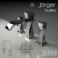
joerger turn
...
joerger , смеситель
http://www.joerger.de/
коллекция turn
артикул 623,30,300
design_connected
$9

Turning desk
...turning desk
designconnected
atelier areti turning desk computer generated 3d model. designed by kerschbaumer, gwendolyn.
3ddd
$1

E-Turn
... скамейка
современная скамейка фирмы kundalini.
модель e-turn.
дизайнер brodie neil.
размеры: h 42 cm l 185 cm w 54 cm
design_connected
$16

Re-turned
...
photo-realistic 3d models of the re-turned table accessories from beller for 3d architectural and interior design presentations.
turbosquid
$15

Turn Ring
...rbosquid
royalty free 3d model turn ring for download as max on turbosquid: 3d models for games, architecture, videos. (1482401)
turbosquid
$15

turning torso
...quid
royalty free 3d model turning torso for download as 3dm on turbosquid: 3d models for games, architecture, videos. (1525931)
turbosquid
$6

RETURN OR TURN
...uid
royalty free 3d model return or turn for download as max on turbosquid: 3d models for games, architecture, videos. (1215382)
7
turbosquid
$6

Rock 7-7
...urbosquid
royalty free 3d model rock 7-7 for download as obj on turbosquid: 3d models for games, architecture, videos. (1647866)
turbosquid
$8

Rock 7-7
...id
royalty free 3d model rock 7-7 for download as ma and fbx on turbosquid: 3d models for games, architecture, videos. (1693416)
design_connected
$16

No 7
...no 7
designconnected
sibast no 7 computer generated 3d model. designed by sibast, helge.
3ddd
$1
Team 7
...team 7
3ddd
team 7
моделилось с кталога team 7
3d_export
$5
hinge 7
...hinge 7
3dexport
hinge 7
turbosquid
$9

IS-7
... available on turbo squid, the world's leading provider of digital 3d models for visualization, films, television, and games.
turbosquid
$12

Calligraphic Digit 7 Number 7
...hic digit 7 number 7 for download as max, obj, fbx, and blend on turbosquid: 3d models for games, architecture, videos. (1389338)
3ddd
free
team 7
...team 7
3ddd
team 7
стол фабрики team 7.
типы размеров /900,1000/x/1750,2000,2250/x/750/
раздвигается +600 или +1200
3ddd
$1

PLANTS 7
...plants 7
3ddd
цветы , горшок
plants 7.. hope u all enjoying the series
3ddd
$1

Pillows #7
...pillows #7
3ddd
подушка , pillows
pillows #7
3ds max 2011,fbx + textures
8
turbosquid
$6

Rock 8-8
...urbosquid
royalty free 3d model rock 8-8 for download as obj on turbosquid: 3d models for games, architecture, videos. (1659393)
3ddd
$1
Italamp 387/8+8
...italamp 387/8+8
3ddd
italamp
люстра italamp 387/8+8
размеры 92x71h
3ddd
$1

8 марта
...8 марта
3ddd
8 марта
кресло 8 марта
design_connected
$16

No 8
...nected
photo-realistic 3d models of the sibast no 8 armchair from sibast for 3d architectural and interior design presentations.
3d_export
$5
hinge 8
...hinge 8
3dexport
hinge 8
3d_export
$5

iphone 8
...iphone 8
3dexport
iphone 8
turbosquid
$69

iPhone 8 and iPhone 8 Plus
... free 3d model iphone 8 and iphone 8 plus for download as max on turbosquid: 3d models for games, architecture, videos. (1202442)
turbosquid
$12

Calligraphic Digit 8 Number 8
...hic digit 8 number 8 for download as max, obj, fbx, and blend on turbosquid: 3d models for games, architecture, videos. (1389341)
3ddd
free

PLANTS 8
...plants 8
3ddd
цветок , горшок
plant 8,,, hope u all like it
3ddd
$1
8 Марта / Amadey
...8 марта / amadey
3ddd
8 марта
8 marta amadey
5
turbosquid
$6

Rock 5-5
...urbosquid
royalty free 3d model rock 5-5 for download as obj on turbosquid: 3d models for games, architecture, videos. (1639063)
3d_export
$5
hinge 5
...hinge 5
3dexport
hinge 5
turbosquid
$10
A-5
... available on turbo squid, the world's leading provider of digital 3d models for visualization, films, television, and games.
turbosquid
$2
A-5
... available on turbo squid, the world's leading provider of digital 3d models for visualization, films, television, and games.
turbosquid
$12

Calligraphic Digit 5 Number 5
...hic digit 5 number 5 for download as max, obj, fbx, and blend on turbosquid: 3d models for games, architecture, videos. (1389333)
3ddd
$1

5 роз
...5 роз
3ddd
5 роз в стеклянной вазе
design_connected
$11

iPhone 5
...iphone 5
designconnected
apple iphone 5 computer generated 3d model.
3ddd
$1
Lola 5
...lola 5
3ddd
miniforms
lola 5 miniforms 300*65*134
3ddd
$1
Nexus 5
...dd
nexus , phone , телефон
google nexus 5 phone
3d_ocean
$15
iPhone 5
...iphone 5
3docean
3d 4d apple cinema iphone model modeling phone screen texture
iphone 5 3d model and texture realistic iphone 5.