Thingiverse

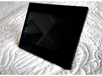
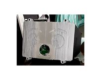
7" Touch screen enclosure (pcb800099) and mounting by atanasovgoran
by Thingiverse
Last crawled date: 3 years, 1 month ago
UPDATE 21-JAN-2019: Fixed model faces, it should slice correctly now.
UPDATE 02-JAN-2018: Added a 5" version after request. Untested, PCBs might be the other way around...
------------------------------- Because of limited space, the cable grooves have been removed. Some other changes have been made. There is no mounting position for Touch pcb.
The desk stand and z axis mount holes are compatible.
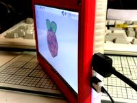
NOTE: If you actually print this can you send me a picture of the front side. I wan't to check the screen alignment in relation to the frame. I have printed a really early version where it wasn't aligned.
I made this for my personal use and decided to share it. It is provided as is, with no guarantee that it will fit your display. It should fit the results of the ebay search provided (both the touchscreen and display only variants.
https://www.ebay.com/sch/i.html?_from=R40&_trksid=p2047675.m570.l1313.TR0.TRC0.H0.X7%27%27+HDMI+HD+1024x600+Touch+Screen+Display+Module+Board+Kit+Set+For+Raspberry+Pi.TRS0&_nkw=7%27%27+HDMI+HD+1024x600+Touch+Screen+Display+Module+Board+Kit+Set+For+Raspberry+Pi&_sacat=0
The design accommodates a few different ways of mounting.
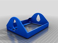
Wall hanger (A 3D printed optional part provided)
Desk stand (A 3D printed optional part provided)\
VESA 75mm mount
Single screw on the bottom side (no guarantees that the plastic could support the weight without breaking.
Multiple holes on the back that provide you with the ability to use your own design for a mount.
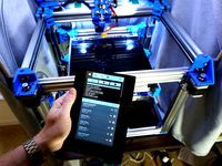
A Z-Axis mount (For a personal project of mine to have the RPi on my reprap with a touchscreen)
UPDATES:
1.The front part wasn't able to handle the screw pressure so I had to drill out the holes. Perhaps some cosmetic Hex cup nuts would fix the issue.
A: I increased the length of the screw hole on the front panel. they should hold now.
B: Also I decreased the size of the hole so the metal inserts shouldn't be required any more.
A: Added a hole next to the buttons for the ir sensor (you might need to bend the sensor slightly)
B: Moved the main driver board so it better aligns with the LCD flat flex cable.
C: Added a new screw hole so that that the case closes better.
D: Reduced the size of the buttons so that they don't misclick if you tighten the case.
E: Finalised the Z-axis mount. (8mm smooth rod mount)
F: Converted the Groups to components in the *.skp file so that changes to one of the "views" are automatically transferred to the others.
G: Modified the Z-axis clamp (8mm rod clamp) so it doesn't interfere with the cable "tie"
Modified the wall hanger for better structural strength.
UPDATE 02-JAN-2018: Added a 5" version after request. Untested, PCBs might be the other way around...
------------------------------- Because of limited space, the cable grooves have been removed. Some other changes have been made. There is no mounting position for Touch pcb.
The desk stand and z axis mount holes are compatible.
NOTE: If you actually print this can you send me a picture of the front side. I wan't to check the screen alignment in relation to the frame. I have printed a really early version where it wasn't aligned.
I made this for my personal use and decided to share it. It is provided as is, with no guarantee that it will fit your display. It should fit the results of the ebay search provided (both the touchscreen and display only variants.
https://www.ebay.com/sch/i.html?_from=R40&_trksid=p2047675.m570.l1313.TR0.TRC0.H0.X7%27%27+HDMI+HD+1024x600+Touch+Screen+Display+Module+Board+Kit+Set+For+Raspberry+Pi.TRS0&_nkw=7%27%27+HDMI+HD+1024x600+Touch+Screen+Display+Module+Board+Kit+Set+For+Raspberry+Pi&_sacat=0
The design accommodates a few different ways of mounting.
Wall hanger (A 3D printed optional part provided)
Desk stand (A 3D printed optional part provided)\
VESA 75mm mount
Single screw on the bottom side (no guarantees that the plastic could support the weight without breaking.
Multiple holes on the back that provide you with the ability to use your own design for a mount.
A Z-Axis mount (For a personal project of mine to have the RPi on my reprap with a touchscreen)
UPDATES:
1.The front part wasn't able to handle the screw pressure so I had to drill out the holes. Perhaps some cosmetic Hex cup nuts would fix the issue.
A: I increased the length of the screw hole on the front panel. they should hold now.
B: Also I decreased the size of the hole so the metal inserts shouldn't be required any more.
A: Added a hole next to the buttons for the ir sensor (you might need to bend the sensor slightly)
B: Moved the main driver board so it better aligns with the LCD flat flex cable.
C: Added a new screw hole so that that the case closes better.
D: Reduced the size of the buttons so that they don't misclick if you tighten the case.
E: Finalised the Z-axis mount. (8mm smooth rod mount)
F: Converted the Groups to components in the *.skp file so that changes to one of the "views" are automatically transferred to the others.
G: Modified the Z-axis clamp (8mm rod clamp) so it doesn't interfere with the cable "tie"
Modified the wall hanger for better structural strength.
Similar models
thingiverse
free
7" Waveshare LCD Enclosure Standalone Remix by Paran0ic
...port.
i plan to design a support like normal computer lcd display. now i use very simple support.
openscad source files attached.
thingiverse
free
7" Waveshare LCD Enclosure and Mount by CapnBry
...adapter with an ultraslim hdmi cable and micro usb down angle cable.
automatic backlight control can be added via a one-wire mod.
thingiverse
free
7" HDMI Screen Mount by andychud
...&sprefix=7+inch+hdmi+touc%2caps%2c375&sr=8-5
https://www.ebay.com/itm/221709931883?hash=item339ef1156b:g:xeuaaoswxe5gcoog
thingiverse
free

7" Display TFT Monitor AT070TN90 by Dareckus
...nnolux 7" inch raspberry pi lcd touch screen display tft monitor at070tn90 with touchscreen kit hdmi vga input driver board.
thingiverse
free
Case for AdaFruit 7" HDMI 800x480 Display with Touch by Bradley
...s.
i needed something i could use to throw in a backpack for portable, "just in case" use of the module.
enjoy!
thingiverse
free

TouchScreen 7" Case by denkyem
...vesa 75x75 holes, so it can be use with some vesa mount support or we can mount a raspberry pi case on it (didn't tested yet)
thingiverse
free

Anti-Wobbling Z-axis Geeetech Prusa I3 (The screw holes rotated ) by thatretroaussie
... clone's z axis wobble problem but, the holes for the print wern't aligned properly for the ctc 13482's z axis mount.
thingiverse
free

Eleduino 7" TFT Front for Raspberry Pi by JPgxuAHFR22RQo
...t side to cover the connectionports (hdmi/usb). i will use it to add some triggers/buttons too (to turn off/on the lcd or light).
thingiverse
free

5" 800x480 HDMI Display shell by giasone
...nformation about the display or to buy it please refer to http://www.watterott.com/en/5-800x480-hdmi-display-with-resistive-touch
thingiverse
free

Display Stand for 5" LCD Monitor by StrainedCMOS
...f the computer case.
nothing fancy for the design but just meant to keep the screen in a visible place with no exposed wiring.
Pcb800099
thingiverse
free

Case for PCB800099 with AT070N90 V.1 LCD by chooze
...0n90 v.1 lcd by chooze
thingiverse
housing for the chinese electronics kit. 7 inch matrix at070n90 v.1 and pcb800099-v.9 boards.
thingiverse
free

PCB800099-v9 Housing by jovial_cynic
...fine.
i printed both the new version (1.2) and the lid on their sides to reduce warping when printing in abs. i also used a raft.
thingiverse
free

7'' LCD + controller stand by diegotagoz
...7'' lcd + controller device. the product code is pcb800099v9. including the inventor...
thingiverse
free

Raspberry 7" Display Frame by robingii
...pcb at the rear display = 7d-cpt-tv-50pin pcb = pcb800099 ...
thingiverse
free

Raspberry 7" Display Frame v2 by robingii
...backward compatible with v1 display = 7d-cpt-tv-50pin pcb = pcb800099 ...
thingiverse
free

8 inch HDMI screen for Trinoculaire Stereo Microscoop by alex1970
...ips display with number hj080ia-01e in combination with the pcb800099v.9 controller pcb with its keyboard. it has a special...
thingiverse
free
7 inch vr head mounted display by justsomeone
...parts from ebay. i used 1280x800 lcd panel with pcb800099 controller board with 5x aspherical lenses. for headtracking i...
thingiverse
free

Customizable Case to recycle LCD Panel by llegoff
...lvds channel&width of the lcd panel (ex: v29, v56, pcb800099 nt68676, z.vst.3463.a1, ....)contrôleur lcd universel programmé pour la résolution,...
3dwarehouse
free

lcd controller pcb800099
... location of the electronic components on the board may not exactly match. the size of the board and bore holes are given exactly
Atanasovgoran
thingiverse
free

Comb with my name by atanasovgoran
...comb with my name by atanasovgoran
thingiverse
this is a personal file
thingiverse
free

Puppet head. by atanasovgoran
...puppet head. by atanasovgoran
thingiverse
this is for personal backup. you can use it if you want, but wont make a lot of sense
thingiverse
free

Fletcher paspartu cutter Stop by atanasovgoran
...fletcher paspartu cutter stop by atanasovgoran
thingiverse
fletcher paspartu cutter stop
thingiverse
free

Minimal Headphone stand (Philips SHP1900) by atanasovgoran
...s shp1900) by atanasovgoran
thingiverse
minimal headphone stand (not sutable for most headphones - designed for philips shp1900)
thingiverse
free

A mod of Klots. (Requires screws) by atanasovgoran
...an
thingiverse
this is an edit of "klöts (quick shoe ties)" with screws
ability to use 3 different color combinations.
thingiverse
free

Motion Sensor box mount mod by atanasovgoran
...motion sensor box mount mod by atanasovgoran
thingiverse
i made some mods for the base of hc-sr501 pir motion sensor box mount.
thingiverse
free

Mic stand base by atanasovgoran
...com/tree-new-bee-microphone-tnb-arm01/dp/b01ebdzhnq/ref=sr_1_4?ie=utf8&qid=1510771555&sr=8-4&keywords=microphone+arm)
thingiverse
free

Shard light base by atanasovgoran
...e.
i would suggest to use a wood filament.
idea from the video of diy perks in youtubehttps://www.youtube.com/watch?v=kgpghsjhkzu
thingiverse
free

Small Organization Boxes by atanasovgoran
...icture
either way, it gave me the idea for this "project"
super simple, print what you need, and assemble them together
thingiverse
free

Cable loop mount by atanasovgoran
...ily, so i decided to design my own version.
the "27-cable-loops.stl" should fit in a 200mmx200mm (8x8") print bed.
Enclosure
3d_export
free
electrical enclosure
...l enclosure where electrical devices like (relays, contactors, busbars ) are kept in order to protect from hazardous environment.
turbosquid
$100
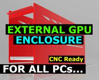
GPU Enclosure
...yalty free 3d model gpu enclosure for download as obj and stl on turbosquid: 3d models for games, architecture, videos. (1381061)
3d_export
$5
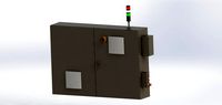
Electrical Enclosure
...ed. also has tower lights attaced on the top.<br>file format that are available:<br>.step<br>.obj<br>.stl
archive3d
free
Enclosure 3D Model
...closure 3d model
archive3d
shower enclosure-acquarius- 3d model for interior 3d visualization.
archive3d
free
Enclosure 3D Model
...enclosure 3d model
archive3d
shower enclosure-omega- 3d model for interior 3d visualization.
archive3d
free
Enclosure 3D Model
...enclosure 3d model
archive3d
shower enclosure-vega - 3d model for interior 3d visualization.
archive3d
free
Enclosure 3D Model
...enclosure 3d model
archive3d
shower enclosure-zenith - 3d model for interior 3d visualization.
turbosquid
$20
shower enclosure
... available on turbo squid, the world's leading provider of digital 3d models for visualization, films, television, and games.
turbosquid
$14
Dumpster Enclosure
... available on turbo squid, the world's leading provider of digital 3d models for visualization, films, television, and games.
turbosquid
$25
3d printer enclosure
... model 3d printer enclosure for download as ipt, skp, and fbx on turbosquid: 3d models for games, architecture, videos. (1634310)
Touch
3ddd
$1

Touch
...touch
3ddd
touch , альфа банк
электронный терминал для очереди
3ddd
$1

GSG / Touch
... ванна
http://www.ceramicagsg.com/sanitaryware-touch/bathtub-touch-free-standing.html
turbosquid
$10

Oculus Touch
...squid
royalty free 3d model oculus touch for download as skp on turbosquid: 3d models for games, architecture, videos. (1462433)
turbosquid
$64

iPod Touch
...ty free 3d model ipod touch for download as 3ds, max, and obj on turbosquid: 3d models for games, architecture, videos. (1299603)
3ddd
$1

iPod Touch 5
...ipod touch 5
3ddd
apple , плеер
модель ipod touch 5
3ddd
$1

Asnaghi "Touch"
...asnaghi "touch"
3ddd
asnaghi , touch
фабрика: asnaghi
модель: touch
3ddd
free
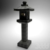
Japanese stone touch
...japanese stone touch
3ddd
фонарь
japanese stone garden touch
японский садовый фонарь
икеокоми-гата
3d_ocean
$15
IPOD TOUCH 5
...apple blender ipad iphone ipod mp3 nano player touch
3d model of ipod touch 5 in 3 colours. available in .3ds, .blend, .obj, .x3d
3d_ocean
$12
iPod touch 5G
...pod jobs nano steve touch
ipod touch 3d model. formats, fbx, obj, max(2010) textures and materials with multiple colors included.
3ddd
$1
HTC Touch HD
...http://www.gsmarena.com/htc_touch_hd-2525.php фото:http://i.smartphone.ua/img/phones/htc-touch-hd/foto_001.jpg
Screen
archibase_planet
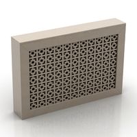
free
Screen
...screen radiator screen radiator enclosure lattice
screen radiator n120315 - 3d model (*.gsm+*.3ds) for interior 3d visualization.
archibase_planet
free

Screen
...screen
archibase planet
screen group display
movie screen - 3d model for interior 3d visualization.
3ddd
$1
Screen
...screen
3ddd
screen
modern dressing wall partition
3d_ocean
$15
HP Screen
...test hp screen. it is has different object, so you can use it as a wall mounted screen or a stand on table. hope you all like it.
3d_export
$10
Accessories screen LCD screen 3D Model
...d screen 3d model
3dexport
accessories screen lcd 3d model interior
accessories screen lcd screen 3d model sunupcg 17831 3dexport
turbosquid
$25
SCREEN
... available on turbo squid, the world's leading provider of digital 3d models for visualization, films, television, and games.
turbosquid
$2
Screen
... available on turbo squid, the world's leading provider of digital 3d models for visualization, films, television, and games.
3d_export
$10
Screen metal screen microwave 3D Model
...ave 3d model
3dexport
screen metal microwave oven 3d model interior
screen metal screen microwave 3d model sunupcg 17847 3dexport
3d_ocean
$5
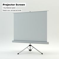
Projector Screen
...hat have presentations. the projector screen consists of an alluminum structure that holds the canvas up. this model can be us...
archive3d
free
Screen 3D Model
...rchive3d
screen folding screen
screen n020811 - 3d model (*.3ds) for interior 3d visualization.
7
turbosquid
$6

Rock 7-7
...urbosquid
royalty free 3d model rock 7-7 for download as obj on turbosquid: 3d models for games, architecture, videos. (1647866)
turbosquid
$8

Rock 7-7
...id
royalty free 3d model rock 7-7 for download as ma and fbx on turbosquid: 3d models for games, architecture, videos. (1693416)
design_connected
$16

No 7
...no 7
designconnected
sibast no 7 computer generated 3d model. designed by sibast, helge.
3ddd
$1
Team 7
...team 7
3ddd
team 7
моделилось с кталога team 7
3d_export
$5
hinge 7
...hinge 7
3dexport
hinge 7
turbosquid
$9

IS-7
... available on turbo squid, the world's leading provider of digital 3d models for visualization, films, television, and games.
turbosquid
$12

Calligraphic Digit 7 Number 7
...hic digit 7 number 7 for download as max, obj, fbx, and blend on turbosquid: 3d models for games, architecture, videos. (1389338)
3ddd
free
team 7
...team 7
3ddd
team 7
стол фабрики team 7.
типы размеров /900,1000/x/1750,2000,2250/x/750/
раздвигается +600 или +1200
3ddd
$1

PLANTS 7
...plants 7
3ddd
цветы , горшок
plants 7.. hope u all enjoying the series
3ddd
$1

Pillows #7
...pillows #7
3ddd
подушка , pillows
pillows #7
3ds max 2011,fbx + textures
Mounting
3d_export
free

mounting bracket
...mounting plate is the portion of a hinge that attaches to the wood. mounting plates can be used indoors, cabinetry and furniture.
turbosquid
$2

MOUNTING
... available on turbo squid, the world's leading provider of digital 3d models for visualization, films, television, and games.
turbosquid
free

Mounts
... available on turbo squid, the world's leading provider of digital 3d models for visualization, films, television, and games.
turbosquid
free

Mount Fuji
...fuji
turbosquid
free 3d model mount fuji for download as obj on turbosquid: 3d models for games, architecture, videos. (1579977)
3d_export
$5

Headphone mount LR
...headphone mount lr
3dexport
headphone mount l+r
turbosquid
$39

Mount rainier
...quid
royalty free 3d model mount rainier for download as fbx on turbosquid: 3d models for games, architecture, videos. (1492586)
turbosquid
$5

pipe mounting
...quid
royalty free 3d model pipe mounting for download as obj on turbosquid: 3d models for games, architecture, videos. (1293744)
turbosquid
$3

Mounting Tires
...uid
royalty free 3d model mounting tires for download as fbx on turbosquid: 3d models for games, architecture, videos. (1708511)
3d_export
$5

Magnetic GoPro Mount
...pro mount
3dexport
cool magnetic mount for gopro. allows you to mount the camera on flat metal surfaces and get exclusive shots.
turbosquid
$5

Stone Mount
...ty free 3d model stone mount for download as ma, obj, and fbx on turbosquid: 3d models for games, architecture, videos. (1370306)