Thingiverse
7 Segment LED Smart Clock by Surrbradl08
by Thingiverse
Last crawled date: 3 years, 1 month ago
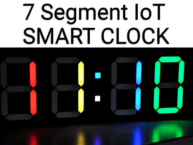
This is a fully 3D printed clock that was designed in Fusion 360. The project is based on Ivan Miranda's Big Digital Clock and was completely re-designed.
If you have any questions or issues feel free contact me
Mini version of the clock here:
https://www.thingiverse.com/thing:3117494
Changelog:
Hotfix 23.10.2018
Uploaded the correct step file for the diffuser
Hotfix 25.09.2018
Uploaded the correct flows file for node-red
Major Software Update: 24.09.2018
Make sure to update all your libraries (3 dashes → manage palette → update)
LOTS OF BUG FIXES
Clock does no longer light up every 6 hours even when turned of
Fixed a bug when clock mode was selected at 00:00 - 00:59 that it would made it show e.g. 24:15
Fixed random reboots
Fixed that alarm wouldn't trigger at the correct time
Fixed a bug that occured when the API-key of openweathermap wasn't set
Fixed error spamming in debug console of Node-red
Fixed that timer would skip 1 second every minute
Fixed bugs that would result in a crash of the clock
and much more...
Removed unnecessary buttons in the UI
Added a settings tab to the UI, the settings section in the ui got moved over there
Clock is now more precise
Timer is now capable of displaying HH:MM and MM:SS format, depending on the remaining time
SOURCE CODE OVERHAUL
Functions are now modular
Added tons of comments
Made the code readable
New functions
Clock/Timer works now more precise (the clock shouldn't be off time more than 2 secs)
Functions utilize much less global variables making the code easier to modify
Weather algorithm got fixed
Fade works more stable now and shouldn't cause a crash anymore
Time is now set in HH:MM:SS before it was HH:MM
Clock now request the time on startup and after connection loss
Custom values now allow to disable digits
Fixed fade-speed levels
Node-red flows are now much more modular, this allows controlling additional clocks
Debug Serial mode for the clock -> debugging can be disabled -> more stability
Brightness slider is now logarithmic
Fixed some typos
Easy way to control more clocks implemented
Time offset should now be persistent
Added Settings page
Improved Alarm Creation
Fixed tons of bugs
Added alternative input formats
Added input check → the user gets informed if the values aren't correct
Adapted the form to the new dashboard plugin update
The alarm triggers now at the correct time :D
and more...
Hotfix: 14.07.2018
Fixed a bug in the arduino code that would cause the shutdown of the clock if the weather gets displayed
Due to an update of the dashboard library some code had to be changed for the timer
Hotfix: 05.07.2018
Updated diffuser_white_28x, fixed the tiny hole on the bottom
All files and photos can be found at: Github
Tested devices
Raspberry Pi 3B
Raspberry Pi B+
Wemos D1 mini
Generic ESP8266 (Led Strip Pin must be changed)
Features
Responsive webinterface
Create alarms
Show current temperature in your region
Configure settings
Display local time
Set individual colors of each digit
Custom scoreboard mode
Control brightness
Save custom colors
Fade colors
Bill of materials
1x Raspberry Pi or any linux machine
1x Wemos D1 mini
1x 1m of WS2812 LED strip with 60 LED's
1x Power supply 5V, 4A
16x M3 * 10-16mm
16x M3 Nuts
1x Power jack adapter
2m Wire
4x Dupont connectors
Estimated total price: 25€ not including the raspberry pi
Tools
Soldering iron
3D Printer
Pliers
Hot glue gun
How to build it
1. 3D-Print
Print Settings
Attention: diffuser and dot_diffuser must be printed at 100% infill!
Part
frame
dot_frame
back_cover
dot_back_cover
diffuser
dot_diffuser
Speed
45mm/s
45mm/s
45mm/s
45mm/s
25mm/s
25mm/s
Infill
15%
15%
15%
15%
100%
100%
Layer
0.2mm
0.2mm
0.2mm
0.2mm
0.2mm
0.2mm
Color
Black
Black
Black
Black
White
White
Amount
4
1
4
1
28
2
2. Soldering of the LED-Strips
First the LED strips have to be cut into pieces of 2 LEDs each, then the ends have to be bent until the solder pads are exposed. It is recommended to tape the strips onto a soldering mat or a table and solder the wires afterwards.
Be careful when wiring the dots, only one LED was used for these pieces.
3. Testing the LEDs
Upload the clock_mqtt.ino sketch onto the ESP8266, if the leds don't show 0:0:0:1 after one minute, then you made a mistake or have loose wires somewhere.
4. Assembling the frame
Push in all 30 diffusers, use the 16 M3 screws and nuts to assemble the frame. This step should be self explainatory.
5. Glue in the LEDs
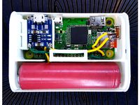
A hot glue gun needs to be used to glue on all LED strips. The start of the LED strip and the ESP8266 must be located on the left when looking at the clock from the front. Afterwards also glue on the microcontroller and the power jack once everything works the way it should. Finally attach the back covers.
Setup
1. Raspberry Pi
You could also install this on any linux machine
In case help with Raspberry Pi is needed, click here.
1. Install Node-RED
bash <(curl -sL https://raw.githubusercontent.com/node-red/raspbian-deb-package/master/resources/update-nodejs-and-nodered)
2. Install npm - this might be already installed
sudo apt-get install nodejs npm -y
3. Install dashboard, openweathermap and mysql
cd $HOME/.node-rednpm install node-red-dashboard
if you get an error try: npm install --unsafe-perm node-red-dashboard
npm install node-red-node-openweathermapnpm install node-red-node-mysql
4. Install mosquitto
sudo apt-get install mosquitto -y
(optional) Setup mosquitto authentication
5. Install mysql
sudo apt-get install mysql-server -y
Just hit OK or RETURN during installation
6. Setup a static ip for your raspberry pi
(recommended) Setup a static ip on your router
or on your Raspberry Pi
7. Create Database clock and account
You will have to create a database named clock to be able to save alarms. Just type into your shell:
mysql -uroot
create database clock;
CREATE USER 'admin'@'localhost' IDENTIFIED BY 'raspberry';
GRANT ALL PRIVILEGES ON clock.* TO 'admin'@'localhost';
FLUSH PRIVILEGES;
quit
2. Node-RED
1. Start node-red
sudo node-red-start
2. Open node-red
http://yourRaspberryIP:1880
3. Import the flows
Click on the 3 dashes in the top right corner → import → clipboard
Enter the code snippet from all_flows_v2.txt and click import
IMPORTANT: Some people reported that the links were not linked, this might be caused by node-red when dealing with different versions.
To fix this, head to the Thingiverse_Communication flow and double click on one of the to link nodes (squared block with an error and one output), check all entries in the list if none of them is checked.
4. Head to the Thingiverse_Settings flow
5. Edit the mqtt node
Set topic to clock
Edit broker and enter localhost in the IP field
If you had set up authentication before, the credentials must be entered in the Security tab
6. Edit the mysql node
Edit the mysql connection
IP: 127.0.0.1
Username: admin
Password: raspberry
Database: clock
7. Click on the latch of the node CREATE TABLE
8. Double click on the node TIME OFFSET
Enter the offset of the time, Germany and Austria would be = 1
9. Get local temperatures from OpenWeatherMap
If temperature output is not needed, just delete the flow Thingiverse_weather and the weather section in the Thingiverse_clock flow.
Head over to OpenWeatherMap and create an account
Click on API-Keys and copy the value
Afterwards copy that key into the openweathermap node in the Thingiverse_weather flow.
Either pick geo-coordinates or city to get the temperatures.
10.Connect to the webinterface
Hit DEPLOY
Now you can connect to the UI via: http://yourRaspberryIP:1880/ui
11. Customize the webinterface
The webinterface is designed to fit the whole screen of the Fire HD 8 Tablet, to fit your phone you have to change the dimensions of the elements.
You can change the position by dragging the elements in the dashboard list.
12. Change theme of the webinterface
You can either choose one of the two default themes or set your own colors.
3. ESP8266
1. Install Arduino IDE
https://www.arduino.cc/en/main/software
2. Add ESP8266 boards to the Arduino IDE
1. Click on preferences
2. Enter under *Additional Board Manager URLs*:
http://arduino.esp8266.com/stable/package_esp8266com_index.json
3. Now head to tools → Board → Boards-Manager
- Search for **esp8266** and install the package
4. Select **WeMos D1 R2 & mini** from the boards list
3. Install libraries
1. Click on sketch → include libary → manage labraries
2. Install *PubSubClient*
3. Install *Adafruit Neopixel*
4. Now open the file clock_mqtt_v2.ino
5. Edit the code
1. Set your WiFi SSID and WiFi password
2. Set **mqtt_server** to your Raspberry Pi's IP-Address
3. If you had set up authentication before, change **mqtt_auth** to 1 and enter your credentials below, otherwise set it to 0
6. Choose the correct COM-Port of the ESP8266 under tools → Port
7. Hit Upload
Congratulations you made it, have fun! ☺
4. My setup
The table i'm using is an Amazon Fire HD 8 with an app called One Page Web Browser, this app can be found here.
If you want to add 2 additional digits, the modified code can be found here
If you have any questions or issues feel free contact me
Mini version of the clock here:
https://www.thingiverse.com/thing:3117494
Changelog:
Hotfix 23.10.2018
Uploaded the correct step file for the diffuser
Hotfix 25.09.2018
Uploaded the correct flows file for node-red
Major Software Update: 24.09.2018
Make sure to update all your libraries (3 dashes → manage palette → update)
LOTS OF BUG FIXES
Clock does no longer light up every 6 hours even when turned of
Fixed a bug when clock mode was selected at 00:00 - 00:59 that it would made it show e.g. 24:15
Fixed random reboots
Fixed that alarm wouldn't trigger at the correct time
Fixed a bug that occured when the API-key of openweathermap wasn't set
Fixed error spamming in debug console of Node-red
Fixed that timer would skip 1 second every minute
Fixed bugs that would result in a crash of the clock
and much more...
Removed unnecessary buttons in the UI
Added a settings tab to the UI, the settings section in the ui got moved over there
Clock is now more precise
Timer is now capable of displaying HH:MM and MM:SS format, depending on the remaining time
SOURCE CODE OVERHAUL
Functions are now modular
Added tons of comments
Made the code readable
New functions
Clock/Timer works now more precise (the clock shouldn't be off time more than 2 secs)
Functions utilize much less global variables making the code easier to modify
Weather algorithm got fixed
Fade works more stable now and shouldn't cause a crash anymore
Time is now set in HH:MM:SS before it was HH:MM
Clock now request the time on startup and after connection loss
Custom values now allow to disable digits
Fixed fade-speed levels
Node-red flows are now much more modular, this allows controlling additional clocks
Debug Serial mode for the clock -> debugging can be disabled -> more stability
Brightness slider is now logarithmic
Fixed some typos
Easy way to control more clocks implemented
Time offset should now be persistent
Added Settings page
Improved Alarm Creation
Fixed tons of bugs
Added alternative input formats
Added input check → the user gets informed if the values aren't correct
Adapted the form to the new dashboard plugin update
The alarm triggers now at the correct time :D
and more...
Hotfix: 14.07.2018
Fixed a bug in the arduino code that would cause the shutdown of the clock if the weather gets displayed
Due to an update of the dashboard library some code had to be changed for the timer
Hotfix: 05.07.2018
Updated diffuser_white_28x, fixed the tiny hole on the bottom
All files and photos can be found at: Github
Tested devices
Raspberry Pi 3B
Raspberry Pi B+
Wemos D1 mini
Generic ESP8266 (Led Strip Pin must be changed)
Features
Responsive webinterface
Create alarms
Show current temperature in your region
Configure settings
Display local time
Set individual colors of each digit
Custom scoreboard mode
Control brightness
Save custom colors
Fade colors
Bill of materials
1x Raspberry Pi or any linux machine
1x Wemos D1 mini
1x 1m of WS2812 LED strip with 60 LED's
1x Power supply 5V, 4A
16x M3 * 10-16mm
16x M3 Nuts
1x Power jack adapter
2m Wire
4x Dupont connectors
Estimated total price: 25€ not including the raspberry pi
Tools
Soldering iron
3D Printer
Pliers
Hot glue gun
How to build it
1. 3D-Print
Print Settings
Attention: diffuser and dot_diffuser must be printed at 100% infill!
Part
frame
dot_frame
back_cover
dot_back_cover
diffuser
dot_diffuser
Speed
45mm/s
45mm/s
45mm/s
45mm/s
25mm/s
25mm/s
Infill
15%
15%
15%
15%
100%
100%
Layer
0.2mm
0.2mm
0.2mm
0.2mm
0.2mm
0.2mm
Color
Black
Black
Black
Black
White
White
Amount
4
1
4
1
28
2
2. Soldering of the LED-Strips
First the LED strips have to be cut into pieces of 2 LEDs each, then the ends have to be bent until the solder pads are exposed. It is recommended to tape the strips onto a soldering mat or a table and solder the wires afterwards.
Be careful when wiring the dots, only one LED was used for these pieces.
3. Testing the LEDs
Upload the clock_mqtt.ino sketch onto the ESP8266, if the leds don't show 0:0:0:1 after one minute, then you made a mistake or have loose wires somewhere.
4. Assembling the frame
Push in all 30 diffusers, use the 16 M3 screws and nuts to assemble the frame. This step should be self explainatory.
5. Glue in the LEDs
A hot glue gun needs to be used to glue on all LED strips. The start of the LED strip and the ESP8266 must be located on the left when looking at the clock from the front. Afterwards also glue on the microcontroller and the power jack once everything works the way it should. Finally attach the back covers.
Setup
1. Raspberry Pi
You could also install this on any linux machine
In case help with Raspberry Pi is needed, click here.
1. Install Node-RED
bash <(curl -sL https://raw.githubusercontent.com/node-red/raspbian-deb-package/master/resources/update-nodejs-and-nodered)
2. Install npm - this might be already installed
sudo apt-get install nodejs npm -y
3. Install dashboard, openweathermap and mysql
cd $HOME/.node-rednpm install node-red-dashboard
if you get an error try: npm install --unsafe-perm node-red-dashboard
npm install node-red-node-openweathermapnpm install node-red-node-mysql
4. Install mosquitto
sudo apt-get install mosquitto -y
(optional) Setup mosquitto authentication
5. Install mysql
sudo apt-get install mysql-server -y
Just hit OK or RETURN during installation
6. Setup a static ip for your raspberry pi
(recommended) Setup a static ip on your router
or on your Raspberry Pi
7. Create Database clock and account
You will have to create a database named clock to be able to save alarms. Just type into your shell:
mysql -uroot
create database clock;
CREATE USER 'admin'@'localhost' IDENTIFIED BY 'raspberry';
GRANT ALL PRIVILEGES ON clock.* TO 'admin'@'localhost';
FLUSH PRIVILEGES;
quit
2. Node-RED
1. Start node-red
sudo node-red-start
2. Open node-red
http://yourRaspberryIP:1880
3. Import the flows
Click on the 3 dashes in the top right corner → import → clipboard
Enter the code snippet from all_flows_v2.txt and click import
IMPORTANT: Some people reported that the links were not linked, this might be caused by node-red when dealing with different versions.
To fix this, head to the Thingiverse_Communication flow and double click on one of the to link nodes (squared block with an error and one output), check all entries in the list if none of them is checked.
4. Head to the Thingiverse_Settings flow
5. Edit the mqtt node
Set topic to clock
Edit broker and enter localhost in the IP field
If you had set up authentication before, the credentials must be entered in the Security tab
6. Edit the mysql node
Edit the mysql connection
IP: 127.0.0.1
Username: admin
Password: raspberry
Database: clock
7. Click on the latch of the node CREATE TABLE
8. Double click on the node TIME OFFSET
Enter the offset of the time, Germany and Austria would be = 1
9. Get local temperatures from OpenWeatherMap
If temperature output is not needed, just delete the flow Thingiverse_weather and the weather section in the Thingiverse_clock flow.
Head over to OpenWeatherMap and create an account
Click on API-Keys and copy the value
Afterwards copy that key into the openweathermap node in the Thingiverse_weather flow.
Either pick geo-coordinates or city to get the temperatures.
10.Connect to the webinterface
Hit DEPLOY
Now you can connect to the UI via: http://yourRaspberryIP:1880/ui
11. Customize the webinterface
The webinterface is designed to fit the whole screen of the Fire HD 8 Tablet, to fit your phone you have to change the dimensions of the elements.
You can change the position by dragging the elements in the dashboard list.
12. Change theme of the webinterface
You can either choose one of the two default themes or set your own colors.
3. ESP8266
1. Install Arduino IDE
https://www.arduino.cc/en/main/software
2. Add ESP8266 boards to the Arduino IDE
1. Click on preferences
2. Enter under *Additional Board Manager URLs*:
http://arduino.esp8266.com/stable/package_esp8266com_index.json
3. Now head to tools → Board → Boards-Manager
- Search for **esp8266** and install the package
4. Select **WeMos D1 R2 & mini** from the boards list
3. Install libraries
1. Click on sketch → include libary → manage labraries
2. Install *PubSubClient*
3. Install *Adafruit Neopixel*
4. Now open the file clock_mqtt_v2.ino
5. Edit the code
1. Set your WiFi SSID and WiFi password
2. Set **mqtt_server** to your Raspberry Pi's IP-Address
3. If you had set up authentication before, change **mqtt_auth** to 1 and enter your credentials below, otherwise set it to 0
6. Choose the correct COM-Port of the ESP8266 under tools → Port
7. Hit Upload
Congratulations you made it, have fun! ☺
4. My setup
The table i'm using is an Amazon Fire HD 8 with an app called One Page Web Browser, this app can be found here.
If you want to add 2 additional digits, the modified code can be found here
Similar models
thingiverse
free
Raspberry Pi - Camera - Sense Hat - Node Red - Octopi - Web Dashboard - Perfect for Remix to other Projects by Padi89
...ted all the time.
check link for serial communication problems!https://discourse.octoprint.org/t/my-new-bq-hephestos-2-setup/1248
thingiverse
free

Homebridge - Raspberry Pi Zero W Enclosure by austin_trujillo
...ip-address>:8080
congrats! you have successfully setup homebridge. for additional support, visit the official homebridge wiki.
thingiverse
free

WIP SSD pi holder
...//oshpark.com/shared_projects/h42oy4rz
the rgb code: link
can control:
5v led strips.
12v led strips
5v addressable strips
thingiverse
free

Pi Pan Tilt Camera Add On by Amilious
... start
this is incomplete will update soon
no octoprint installation:
instructions
updates
update 01/16/2018
uploaded project.
thingiverse
free

Pi Cam Cover for Neopixel 12 Ring
...55))
off.py contains the following:
import board
import neopixel
pixels = neopixel.neopixel(board.d18, 12)
pixels.fill((0, 0, 0))
thingiverse
free
Raspberry Pi Car HMI Enclosure
...rks-cad-raspberry-pi-raspberrypi-rpi-1
30x30x10 dc fan : missing reference at the moment. will update link as soon as i find it.
thingiverse
free
Open CV Handheld Scanner by rolf3d
...t til conf_swapsize=100)
/opencv/build$ sudo /etc/init.d/dphys-swapfile stop
/opencv/build$ sudo /etc/init.d/dphys-swapfile start
thingiverse
free
Raspberry Pi Zero Node by blankdesign
... for ways i can improve this design or any better components i could use for the charging board please leave a comment.
have fun!
3dwarehouse
free

CJMCU 2812-8
...cjmcu 2812-8
3dwarehouse
rgb led strip. hard pcb 1 x 8 arduino, raspberry pi
thingiverse
free

Cubic Fractal Chain by sskwirrel
...res the frameworx module to be install (npm install frameworx).
for more information see
frameworx on github
frameworx on npm
Surrbradl08
thingiverse
free

Twisted Lampshade by Surrbradl08
...twisted lampshade by surrbradl08
thingiverse
printed in 100% infill with pla.
thingiverse
free

Microcube 40mm Fan Connector by Surrbradl08
...rbradl08
thingiverse
fan duct adjusted to fit a 40mm fan for the microcube.
microcube: https://www.thingiverse.com/thing:1938877
thingiverse
free

Simple stand for pizza cutter bike by Surrbradl08
... just a simple stand for pizza cutter bike.
here is the link where you can buy the bike:http://s.click.aliexpress.com/e/byzqopzw
thingiverse
free

Case for Arduino Mega 2560 with LiTec Shield by Surrbradl08
... and power connector
update: 19.04.2018:
added a complete overhaul of the design
added multi material variant
removed old design
thingiverse
free

Dual extrusion Y-Splitter with thread by Surrbradl08
...fast insert 105mmg1 e5 f300; 5mm/s feed 5mmg92 e0; zero extruderg1 z-1 f420; return z to resume printingg90; absolute coordinates
thingiverse
free

Twisted Lamp, Remixes and Additions by DorffMeister
...look of the "twisted wifi controlled desk lamp" by surrbradl08 but i didn't want to do all the work...
thingiverse
free

Big digital clock, time from web, temperature and humidity
...well readable from far, so i deeply remixed the surrbradl08 leonvandenbeukel ans ivanmiranda ones hardware and software to my...
thingiverse
free

Big digital clock v2, time from web, temperature and humidity
...well readable from far, so i deeply remixed the surrbradl08 leonvandenbeukel ans ivanmiranda ones hardware and software to my...
thingiverse
free

10mm slide in LED strip mount for Kossel Linear Plus 10 degree angle by Gnattycole
...actually scratch drawn but i took the inspiration from surrbradl08#39;s design so only fair i acknowledge the original author...
Segment
archibase_planet
free

Segment
...segment
archibase planet
playground sports ground
segment 1 - 3d model (*.gsm+*.3ds) for interior 3d visualization.
archibase_planet
free

Segment
...segment
archibase planet
playground chute slide
segment 2 - 3d model (*.gsm+*.3ds) for interior 3d visualization.
archibase_planet
free

Segment
...segment
archibase planet
playground sports ground
segment 3 - 3d model (*.gsm+*.3ds) for interior 3d visualization.
archibase_planet
free
Segment
...segment
archibase planet
sports ground playground
segment 4 - 3d model (*.gsm+*.3ds) for interior 3d visualization.
archibase_planet
free

Segment
...segment
archibase planet
playground sports ground
segment 5 - 3d model (*.gsm+*.3ds) for interior 3d visualization.
archibase_planet
free

Segment
...segment
archibase planet
chute playground slide
segment 6 - 3d model (*.gsm+*.3ds) for interior 3d visualization.
archibase_planet
free

Segment
...segment
archibase planet
sports ground playground
segment 8 - 3d model (*.gsm+*.3ds) for interior 3d visualization.
archibase_planet
free

Segment
...segment
archibase planet
playground sports ground
segment 7 - 3d model (*.gsm+*.3ds) for interior 3d visualization.
archibase_planet
free

Segment
...segment
archibase planet
playground sports ground
segment 9 - 3d model (*.gsm+*.3ds) for interior 3d visualization.
archibase_planet
free

Segment
...segment
archibase planet
playground sports ground
segment 10 - 3d model (*.gsm+*.3ds) for interior 3d visualization.
Smart
3ddd
$1

SMART
...smart
3ddd
стул smart
3d_export
$5
smart tv
...smart tv
3dexport
beautiful smart tv
turbosquid
$15

Smart
... available on turbo squid, the world's leading provider of digital 3d models for visualization, films, television, and games.
3ddd
$1
CTSsalotti / Smart
...ctssalotti / smart
3ddd
ctssalotti , угловой
ctssalotti smart 2800х1700
3ddd
$1
Gala Smart раковина
...gala smart раковина
3ddd
gala , smart
производитель gala
модель smart
design_connected
$13

Smart&Sleek
...smart&sleek
designconnected
wisteria smart&sleek computer generated 3d model.
3d_export
$5

Smart 3D Model
...smart 3d model
3dexport
smart car small mercedes
smart 3d model pio33d 67449 3dexport
3d_export
$15
Smart 3D Model
...smart 3d model
3dexport
smart auto car compact_car compat
smart 3d model savmart 95148 3dexport
3d_export
$12

samsung smart tv
...samsung smart tv
3dexport
samsung smart tv
3ddd
$1
Smart
...smart
3ddd
материалы вирей. модель не моя. переделал под вирей просто.
Clock
3d_ocean
$4
Clock
...clock
3docean
clock hand kitchen clock time watch
a clock
archibase_planet
free

Clock
...clock
archibase planet
clock table clock alarm-clock
clock orange - 3d model (*.gsm+*.3ds) for interior 3d visualization.
archibase_planet
free

Clock
...clock
archibase planet
clock table clock alarm-clock
clock yellow - 3d model (*.gsm+*.3ds) for interior 3d visualization.
archibase_planet
free
Clock
...clock
archibase planet
clock alarm-clock
clock n100707 - 3d model for interior 3d visualization.
archibase_planet
free

Clock
...clock
archibase planet
clock table clock
clock - 3d model (*.gsm+*.3ds) for interior 3d visualization.
archibase_planet
free

Clock
...clock
archibase planet
clock striking clock
clock - 3d model (*.gsm+*.3ds) for interior 3d visualization.
archibase_planet
free
Clock
...clock
archibase planet
clock wall clock
clock 1 - 3d model (*.gsm+*.3ds) for interior 3d visualization.
archibase_planet
free
Clock
...clock
archibase planet
clock wall clock
clock 2 - 3d model (*.gsm+*.3ds) for interior 3d visualization.
archibase_planet
free

Clock
...clock
archibase planet
clock wall clock
clock 3 - 3d model (*.gsm+*.3ds) for interior 3d visualization.
archibase_planet
free
Clock
...clock
archibase planet
alarm clock alarm-clock
clock - 3d model (*.gsm+*.3ds) for interior 3d visualization.
Led
3d_export
$5
led
...led
3dexport
the led is cut with all the parts.
3ddd
$1
Monacor / PARL56DMX / LED-320RGBW / LED-345RGBW / LED-300RGB
... прожектор
http://www.monacor.dk/
parl56dmx
led-320rgbw
led-345rgbw
led-300rgb
turbosquid
$10
LED
...led
turbosquid
free 3d model led for download as blend on turbosquid: 3d models for games, architecture, videos. (1691856)
3d_export
$5

led lamp
...led lamp
3dexport
led lamp, brightness animation
3ddd
free
leds-c4
...leds-c4
3ddd
leds-c4
современный торшер
3ddd
free
leds-c4
...leds-c4
3ddd
leds-c4
настольный лампа
turbosquid
$19
LED
... available on turbo squid, the world's leading provider of digital 3d models for visualization, films, television, and games.
turbosquid
$12
Led
... available on turbo squid, the world's leading provider of digital 3d models for visualization, films, television, and games.
turbosquid
free

LED
... available on turbo squid, the world's leading provider of digital 3d models for visualization, films, television, and games.
turbosquid
free
LED
... available on turbo squid, the world's leading provider of digital 3d models for visualization, films, television, and games.
7
turbosquid
$6

Rock 7-7
...urbosquid
royalty free 3d model rock 7-7 for download as obj on turbosquid: 3d models for games, architecture, videos. (1647866)
turbosquid
$8

Rock 7-7
...id
royalty free 3d model rock 7-7 for download as ma and fbx on turbosquid: 3d models for games, architecture, videos. (1693416)
design_connected
$16

No 7
...no 7
designconnected
sibast no 7 computer generated 3d model. designed by sibast, helge.
3ddd
$1
Team 7
...team 7
3ddd
team 7
моделилось с кталога team 7
3d_export
$5
hinge 7
...hinge 7
3dexport
hinge 7
turbosquid
$9

IS-7
... available on turbo squid, the world's leading provider of digital 3d models for visualization, films, television, and games.
turbosquid
$12

Calligraphic Digit 7 Number 7
...hic digit 7 number 7 for download as max, obj, fbx, and blend on turbosquid: 3d models for games, architecture, videos. (1389338)
3ddd
free
team 7
...team 7
3ddd
team 7
стол фабрики team 7.
типы размеров /900,1000/x/1750,2000,2250/x/750/
раздвигается +600 или +1200
3ddd
$1

PLANTS 7
...plants 7
3ddd
цветы , горшок
plants 7.. hope u all enjoying the series
3ddd
$1

Pillows #7
...pillows #7
3ddd
подушка , pillows
pillows #7
3ds max 2011,fbx + textures