Thingiverse
4x 18650 Charging Station w/ 5v1a Single Cell Lipo Chargers by memisis
by Thingiverse
Last crawled date: 3 years ago
Summary
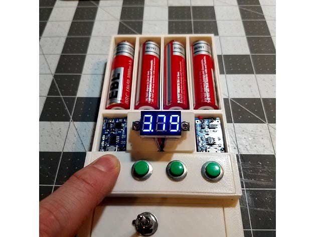
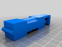
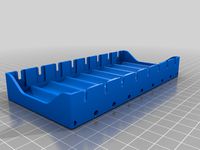
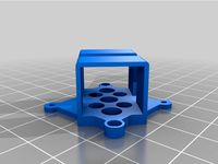
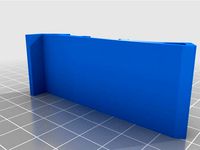
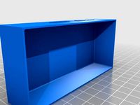
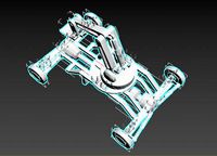
This is a 4 bay 18650 charging station that allows the user to check the voltage of each battery cell when power to the charging unit is off.
Parts Needed
(4x) 4v1a Single cell lipo chargers https://www.amazon.com/gp/product/B071RG4YWM/ref=oh_aui_detailpage_o03_s00?ie=UTF8&psc=1
(4x) Batter case (to obtain -spring and +terminal with wires) https://www.amazon.com/gp/product/B013DUOJV4/ref=oh_aui_detailpage_o05_s01?ie=UTF8&psc=1
(4x) Momentary Switch Buttons https://www.amazon.com/WGCD-Momentary-Button-Switch-Thread/dp/B06XFWVFR9/ref=sr_1_38?ie=UTF8&qid=1520473695&sr=8-38&keywords=momentary+push+button+switch
(1x) Voltmeter https://www.amazon.com/gp/product/B00YALV0NG/ref=oh_aui_detailpage_o00_s00?ie=UTF8&psc=1
(10x) M2x6mm Screws
(8x) M2 Nut
Double sided foam tape
26guage silicon wire
Power terminal (I used an XT60)
Possible Parts
Voltage Step-down https://www.amazon.com/gp/product/B071CWMRYD/ref=oh_aui_detailpage_o01_s00?ie=UTF8&psc=1
Toggle Switch https://www.amazon.com/Gikfun-MTS102-Position-Toggle-Arduino/dp/B01BWL7Z44/ref=sr_1_40?ie=UTF8&qid=1520475369&sr=8-40&keywords=toggle+switch
Instructions
Remove the -spring and + terminal from the batter cases
Attatch the -spring and + terminal to the 18650 battery bays
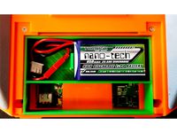
Run the wires into the charging module bay
Run two (2) sets of -&+ wires from the buttons bay into each charging bay
Solder the -spring and + terminal AND one set of -&+ wires from the buttons bay to the BATT -&+ respectively
Solder the remaining pair of -&+ wires to the 5v source on the charging modules
Solder all - wires from the BATT -, AND solder the - from the voltmeter, AND the 5v source - together
Solder the source + to the + source for the charging modules
Solder each BATT + to one side of the push button
Solder the other side of the push buttons AND the + and White cables from voltmeter together
Solder toggle switch to - 5v source to break the circuit via toggle switch if desired
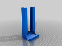
Use double-sided foam tape to affix the charging modules to the printed standoffs
Notes:
Make sure to have a PS that is able to supply 4 amps at 5v. I opted to use a step down with a 24vPS to get to 5v. The part is listed above and is working well with a powered onboard fan. This is thing XXXX.
The user can obtain voltages from each cell by powering off the unit and pressing the buttons one at a time. Pressing more than one button gives you the voltage of both batteries. Pressing the button while the until is powered gives you a powered voltage from the charger.
Hope you enjoy! This was a fun project for me.
This is a 4 bay 18650 charging station that allows the user to check the voltage of each battery cell when power to the charging unit is off.
Parts Needed
(4x) 4v1a Single cell lipo chargers https://www.amazon.com/gp/product/B071RG4YWM/ref=oh_aui_detailpage_o03_s00?ie=UTF8&psc=1
(4x) Batter case (to obtain -spring and +terminal with wires) https://www.amazon.com/gp/product/B013DUOJV4/ref=oh_aui_detailpage_o05_s01?ie=UTF8&psc=1
(4x) Momentary Switch Buttons https://www.amazon.com/WGCD-Momentary-Button-Switch-Thread/dp/B06XFWVFR9/ref=sr_1_38?ie=UTF8&qid=1520473695&sr=8-38&keywords=momentary+push+button+switch
(1x) Voltmeter https://www.amazon.com/gp/product/B00YALV0NG/ref=oh_aui_detailpage_o00_s00?ie=UTF8&psc=1
(10x) M2x6mm Screws
(8x) M2 Nut
Double sided foam tape
26guage silicon wire
Power terminal (I used an XT60)
Possible Parts
Voltage Step-down https://www.amazon.com/gp/product/B071CWMRYD/ref=oh_aui_detailpage_o01_s00?ie=UTF8&psc=1
Toggle Switch https://www.amazon.com/Gikfun-MTS102-Position-Toggle-Arduino/dp/B01BWL7Z44/ref=sr_1_40?ie=UTF8&qid=1520475369&sr=8-40&keywords=toggle+switch
Instructions
Remove the -spring and + terminal from the batter cases
Attatch the -spring and + terminal to the 18650 battery bays
Run the wires into the charging module bay
Run two (2) sets of -&+ wires from the buttons bay into each charging bay
Solder the -spring and + terminal AND one set of -&+ wires from the buttons bay to the BATT -&+ respectively
Solder the remaining pair of -&+ wires to the 5v source on the charging modules
Solder all - wires from the BATT -, AND solder the - from the voltmeter, AND the 5v source - together
Solder the source + to the + source for the charging modules
Solder each BATT + to one side of the push button
Solder the other side of the push buttons AND the + and White cables from voltmeter together
Solder toggle switch to - 5v source to break the circuit via toggle switch if desired
Use double-sided foam tape to affix the charging modules to the printed standoffs
Notes:
Make sure to have a PS that is able to supply 4 amps at 5v. I opted to use a step down with a 24vPS to get to 5v. The part is listed above and is working well with a powered onboard fan. This is thing XXXX.
The user can obtain voltages from each cell by powering off the unit and pressing the buttons one at a time. Pressing more than one button gives you the voltage of both batteries. Pressing the button while the until is powered gives you a powered voltage from the charger.
Hope you enjoy! This was a fun project for me.
Similar models
thingiverse
free

Ender 3 Voltage Regualtion box with switch
...3_s00?ie=utf8&psc=1
jst-xh: https://www.amazon.com/gp/product/b07x9mj8g2/ref=ppx_yo_dt_b_asin_title_o04_s02?ie=utf8&psc=1
thingiverse
free

Desk Fan by NebNorse
...lpages04?ie=utf8&psc=1
motor control: https://www.amazon.com/gp/product/b01cnl6imc/ref=od_aui_detailpages04?ie=utf8&psc=1
thingiverse
free

Travel/Home Charging Station
...p/product/b006zb30ve/ref=ppx_yo_dt_b_asin_title_o08_s00?ie=utf8&psc=1
power supply: hp hstns-pl14 (generic p/n: 499249-201)
thingiverse
free
Power supply enclosure for DROK voltage regulator. by isaacmedford
..._detailpage_o00_s01?ie=utf8&psc=1https://www.amazon.com/gp/product/b01ioq77ny/ref=oh_aui_detailpage_o01_s00?ie=utf8&psc=1
thingiverse
free

Power supply cover with voltage meter by johnnyz7390
...tf8&psc=1
switch and power plug:
http://www.amazon.com/gp/product/b008ds1nc0/ref=oh_details_o08_s00_i06?ie=utf8&psc=1
thingiverse
free
50A Power Supply Cover W/LCD Display by hkgary_g
...lpage_o06_s01?ie=utf8&psc=1
power socket
www.amazon.com/gp/product/b06xnmt3wl/ref=oh_aui_detailpage_o06_s00?ie=utf8&psc=1
thingiverse
free

Guitar Pickup Winder
...=utf8&psc=1
speed adjustmenthttps://www.amazon.com/gp/product/b07vpnhs5j/ref=ppx_yo_dt_b_asin_title_o02_s01?ie=utf8&psc=1
thingiverse
free
Hand Mixer by OM3
...e?ie=utf8&psc=1
power supplyhttps://www.amazon.com/gp/product/b01461mogq/ref=ppx_yo_dt_b_search_asin_title?ie=utf8&psc=1
thingiverse
free

Formd T1 USB Mounting Plate by zke96
...//www.amazon.com/gp/product/b01i9kduc2/ref=ppx_yo_dt_b_search_asin_title?ie=utf8&psc=1
(should fit any 16mm momentary switch)
thingiverse
free

Esk8 Enclosure Bottom Mount Switch Plate by mmaner
...mp; power switch slots.
voltmeter: https://www.amazon.com/gp/product/b071hw4qhl/ref=oh_aui_detailpage_o04_s00?ie=utf8&psc=1
Memisis
thingiverse
free

W1209 Temperature Control Plus Step Down Module Housing by memisis
...ut a power in / fan out port on the side of the unit that i needed it at. you can easily put holes wherever you like by drilling.
thingiverse
free

Proteus Solder Station - 80mm fan by ProteanMan
...from their makes of the solder station. streetmaker: https://www.thingiverse.com/make:474512 memisis https://www.thingiverse.com/make:491823 safety disclaimer: the purpose is to pull fumes...
5V1A
thingiverse
free

5V1A Dual Power Port by Simonwlchan
...cools the extruder.
http://www.thingiverse.com/thing:941263http://www.thingiverse.com/thing:875471
what can you use this for?
thingiverse
free
Supercool your Printrbot Extruder by Simonwlchan
...a make-shift 5v connection re-purposed from an old iphone 5v1a plug and usb cable, which also supports another fan...
thingiverse
free
Gopro Hero 6/7 backpack for Tina Whoop by ezk8
...to use the onboard bec, i'm using a pololu 5v1a regulator instead. the bec board killed my gopro power...
thingiverse
free

Whoop Drone Cross 4S Night Flight Acro by Microdure
...mha or 4s 1000 mha mini controleur f4 betaflight :http://www.banggood.com/fr/mini-acro-f4-betaflight-flight-controller-buil-in-pdb-5v1abec-with-micro-buzzer-p-1110441.html?p=ld020411878172015024 esc 4x 20amp bheli s v2:http://www.banggood.com/fr/racerstar-rs20ax4-v2-20a-bb2-48mhz-blheli_s-2-4s-opto-oneshot42-multishot-4-in-1-esc-for-fpv-racer-p-1080541.html?p=ld020411878172015024 receiver frsky:http://www.banggood.com/fd800-tiny-frsky-8ch-ppmsbus-receiver-compatible-frsky-accst-x9dplusdjtdftdht-for-qx95-qx90-p-1108071.html?p=ld020411878172015024 brusheless...
thingiverse
free

5V Standby PSU Mount/Case/Cover by atanasovgoran
...can turn on/off your printer remotely. i bought a 5v1a psu from ebay almost a year ago, i can't...
thingiverse
free
3D printable antweight battlebot: Bulldog by Bribro12
...(ccw) link: https://www.banggood.com/racerstar-racing-edition-1806-br1806-2280kv-1-3s-brushless-motor-cw-or-ccw-for-250-260-for-rc-drone-fpv-racing-p-1065664.html?p=e01411629100201406t1&custlinkid=1312894 1 × 10a brushless esc link: https://www.banggood.com/rw_rc-10a-brushless-esc-5v1abec-2s-3s-for-rc-models-fixed-wing-airplane-drone-p-1621812.html?p=e01411629100201406t1&custlinkid=1312900 1 × spektrum reveiver (buy only when you already...
grabcad
free

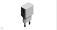
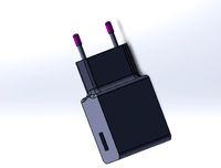
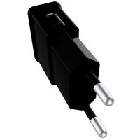
12V to 5V1A power supply and 8x1.5V charger
...12v to 5v1a power supply and 8x1.5v charger
grabcad
solidworks 2012 asm
cults
free

Whoop Drone Cross 4S Night Flight Acro
...or 4s 1000 mha mini controleur f4 betaflight : http://www.banggood.com/fr/mini-acro-f4-betaflight-flight-controller-buil-in-pdb-5v1abec-with-micro-buzzer-p-1110441.html?rmmds=search?p=ld020411878172015024 esc 4x 20amp bheli s v2: http://www.banggood.com/fr/racerstar-rs20ax4-v2-20a-bb2-48mhz-blheli_s-2-4s-opto-oneshot42-multishot-4-in-1-esc-for-fpv-racer-p-1080541.html?rmmds=search?p=ld020411878172015024 receiver frsky:...
18650
3d_export
$10

battery 18650
...battery 18650
3dexport
battery 18650
turbosquid
$10

18650 Li-ion Battery
... available on turbo squid, the world's leading provider of digital 3d models for visualization, films, television, and games.
3d_export
$15
lithium ion 18650 battery
...e up render. - all parts and materials are logically named. other formats ================= - collada (.dae) - autodesk fbx - obj
3d_export
$10

18650 lithium battery
...your software before making a purchase is highly recommend. -in case of problems with the 3d model, do not hesitate to contact me
3d_export
free

solar rechargeable single led flashing light
...light 3dexport unit was design for housing a single 18650 lithium-ion battery and mini solar panel 55mm x 41mm-...
3d_export
$12

Emoji 042 Loudly Crying With Tears
...spec/gloss textures<br>- blend (cycles): metal/roughnes textures<br>geometry:<br>- units: centimeters<br>- polygons: 18650lt;br>- vertex: 18822<br>- triangles: 2<br>- quads: 18648<br>- ngons: 0<br>- vertex...
thingiverse
free
18650
...18650
thingiverse
18650 power supply, vase mode
thingiverse
free
18650 CASE
...18650 case
thingiverse
18650 case!
thingiverse
free
18650 holder
...18650 holder
thingiverse
18650 holder
thingiverse
free
18650 dispenser
...18650 dispenser
thingiverse
18650 dispenser for 10 batteries.
Lipo
thingiverse
free
Soporte lipo
...soporte lipo
thingiverse
customizable lipo stand
thingiverse
free
Copterframe Lipo Adapter for bigger Lipos by heckmic
...o adapter for bigger lipos by heckmic
thingiverse
copterframe lipo adapter for bigger lipos
look at michael-heck.net for more.
thingiverse
free

Testeur LIPO / LIPO Tester
...testeur lipo / lipo tester
thingiverse
salut a tous ceux qui sont sur cette page !
thingiverse
free

Lipo Taranis
...lipo taranis
thingiverse
pour lipo gn3 taranis
thingiverse
free
Harvest lipo buckle
...harvest lipo buckle
thingiverse
tpu lipo belt. keep out the frame your lipo straps.
thingiverse
free

lipo box by snoupypop
...lipo box by snoupypop
thingiverse
pour lipo 25c 1s
thingiverse
free
Lipo Stand by Cagatay
...lipo stand by cagatay
thingiverse
6x (12x35mm) lipo compartment
thingiverse
free
Lipo cover for bottom slung lipos by Zugara
...s and battery strap width of 20mm. length of 75mm x 30mm wide, 17mm height.
stl is for hollow print, so adjust yours accordingly.
thingiverse
free
boite lipo by micma
...boite lipo by micma
thingiverse
boite pour accu lipo tattu 850mha
thingiverse
free
LiPo Holder for Taranis
... taranis
thingiverse
this is my lipo holder for taranis radios. i use it with 850 mah lipo's, but others may also work fine.
4X
turbosquid
$55

CandyBowls 4x
...yalty free 3d model candybowls 4x for download as lwo and obj on turbosquid: 3d models for games, architecture, videos. (1712984)
3d_export
$5

ACOG 4X
...acog 4x
3dexport
turbosquid
$48

DonutsCollection 4x
...d model donutscollection 4x for download as lwo, fbx, and obj on turbosquid: 3d models for games, architecture, videos. (1708202)
turbosquid
$10

4x Scope
...ty free 3d model 4x scope for download as blend, fbx, and obj on turbosquid: 3d models for games, architecture, videos. (1695418)
turbosquid
$10

4x Scope
...ty free 3d model 4x scope for download as blend, obj, and fbx on turbosquid: 3d models for games, architecture, videos. (1695416)
turbosquid
$10

4x Scope
...ty free 3d model 4x scope for download as blend, fbx, and obj on turbosquid: 3d models for games, architecture, videos. (1695407)
turbosquid
$48

DonutsCollection 4x 2
...model donutscollection 4x 2 for download as lwo, fbx, and obj on turbosquid: 3d models for games, architecture, videos. (1708541)
turbosquid
$25

Table decor 4x
...d model table decor 4x for download as max, max, fbx, and obj on turbosquid: 3d models for games, architecture, videos. (1668640)
turbosquid
$3

4x scope for sniper rifle
...ty free 3d model 4x scope for sniper rifle for download as ma on turbosquid: 3d models for games, architecture, videos. (1354184)
archive3d
free
Case 4x 3D Model
...case 4x 3d model
archive3d
wardrobe case
Chargers
3d_export
$5
charger
...ers in battle. this is the 18th century meaning of charger, and it’s based on the verb charge and its meaning “rush into battle.”
3d_export
free
Charger
...charger
3dexport
turbosquid
$15

Charger
... available on turbo squid, the world's leading provider of digital 3d models for visualization, films, television, and games.
turbosquid
$3

Charger
...d model charger for download as skp, max, blend, stl, and obj on turbosquid: 3d models for games, architecture, videos. (1654816)
turbosquid
$1
charger
... available on turbo squid, the world's leading provider of digital 3d models for visualization, films, television, and games.
3d_export
$20

dodge charger 1972
...dodge charger 1972
3dexport
dodge charger 1972
3d_export
$20

dodge charger 1969
...dodge charger 1969
3dexport
dodge charger 1969
3d_export
free

dodge charger 1969
...dodge charger 1969
3dexport
dodge charger 1969
3d_export
$18

dodge charger
...dodge charger
3dexport
3d_export
$89
Charger 3D Model
...charger 3d model
3dexport
charger sea transopt industry 3d models
charger 3d model vitaly amurskiy 2286 3dexport
Cell
archibase_planet
free
Cell
...cell
archibase planet
cage cell
cell n050510 - 3d model (*.gsm+*.3ds) for interior 3d visualization.
3d_export
$14

Blood Cells
...poiesis and found in the blood. major types of blood cells include; red blood cells (erythrocytes) white blood cells (leukocytes)
3d_export
$5

cell
...cell
3dexport
turbosquid
$89

Cell
...
royalty free 3d model cell for download as max, obj, and fbx on turbosquid: 3d models for games, architecture, videos. (1225448)
turbosquid
$19

Cell
...
royalty free 3d model cell for download as max, fbx, and obj on turbosquid: 3d models for games, architecture, videos. (1528922)
3d_ocean
$5
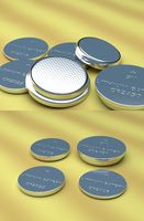
Lithium Cells
...cr2032 cr2450 lithium lithium battery lithium cell power
some lithium cells. cr2032, cr2025, cr2016, cr2450 faces: ca. 65000 each
turbosquid
$45
cell
...yalty free 3d model cell for download as ma, ma, fbx, and obj on turbosquid: 3d models for games, architecture, videos. (1650714)
3d_export
$5

Blood cells
...blood cells
3dexport
blood cells 3d model
3ddd
$1
solar cell
...solar cell
3ddd
солнечная батарея
solar cell
turbosquid
$60

Cell
... available on turbo squid, the world's leading provider of digital 3d models for visualization, films, television, and games.
Charging
3d_export
$7
pneumatic charging car
...pneumatic charging car
3dexport
pneumatic charging car
turbosquid
$1

Charge Sword
...uid
royalty free 3d model charge sword for download as blend on turbosquid: 3d models for games, architecture, videos. (1196298)
turbosquid
$5

Overhead charge
...lty free 3d model overhead charge for download as fbx and obj on turbosquid: 3d models for games, architecture, videos. (1695997)
3d_export
$65

charging station
...charging station
3dexport
simple rendering of the scene file
3d_export
$65

soldiers charge
...soldiers charge
3dexport
simple rendering of the scene file
3d_export
$5
Charging Booth 3D Model
...charging booth 3d model
3dexport
charging booth
charging booth 3d model kanika 60018 3dexport
cg_studio
$30

Electric Vehicle Car Charging Station without Charging Units3d model
...ic vehicle car charging station without charging units 3d model, royalty free license available, instant download after purchase.
turbosquid
$29

Electric Vehicle / Car Charging Station without Charging Units(1)
... available on turbo squid, the world's leading provider of digital 3d models for visualization, films, television, and games.
3d_export
$5
glass battery with charge divisions
...glass battery with charge divisions
3dexport
glass battery with charge divisions, materials for eevee, under the subdiv.
turbosquid
$39

JBL Charge 3
... free 3d model jbl charge 3 for download as max, fbx, and obj on turbosquid: 3d models for games, architecture, videos. (1698833)
Station
3d_export
$5
station
...station
3dexport
station
archibase_planet
free
Station
...station
archibase planet
railroad station railway station bay
railway station n160707 - 3d model for interior 3d visualization.
archibase_planet
free
Station
...station
archibase planet
intercom station equipment
intercom station - 3d model for interior 3d visualization.
archibase_planet
free
Station
...station
archibase planet
station
station n260108 - 3d model (*.gsm+*.3ds) for interior 3d visualization.
3d_export
$5
Station
...station
3dexport
low poly bus station
archibase_planet
free
Station
...station
archibase planet
building station construction
station n170708 - 3d model(*.gsm+*.3ds) for interior 3d visualization.
archibase_planet
free

Station
...station
archibase planet
bus station bus stop
station 1 - 3d model (*.gsm+*.3ds) for interior 3d visualization.
archibase_planet
free
Station
...station
archibase planet
bus station bus stop
station 2 - 3d model (*.gsm+*.3ds) for interior 3d visualization.
archibase_planet
free
Station
...station
archibase planet
bus station bus stop
station 3 - 3d model (*.gsm+*.3ds) for interior 3d visualization.
3d_ocean
$19

Space station
...space station
3docean
space station
space station
Single
3d_export
$5

single sofa single chair
...single sofa single chair
3dexport
single sofa single chair 3d model
3d_export
$5

single sofa single chair
...single sofa single chair
3dexport
single sofa single chair 3d model
3d_export
$5

single fastener
...single fastener
3dexport
single fastener
3ddd
$1

Single FLOU
... sofa , трансформер
диван-трансформер single от итальянского производителя flou
3ddd
$1

bed single
...bed single
3ddd
постельное белье
bed single 190cm*90cm
3ddd
$1

Single Flou
...single flou
3ddd
качественная моделька дивана-трансформера single flou.
3d_ocean
$9

Single sofa
...le sofa
3docean
modern sofa single sofa sofa white sofa.comfortable sofa
single sofa,sofa,modern sofa,white sofa.comfortable sofa
3d_export
free

Single Knife
...single knife
3dexport
a single knife, presumably it was used as one of the throwing knives.
3d_export
free

couch - single
...couch - single
3dexport
low poly single couch with .psd file for personal customization
3d_ocean
$5

Single Sofa
...single sofa
3docean
single sofa made by fabric , wood frame & ss leg
W
3ddd
$1

chair W
...chair w
3ddd
chair w
3ddd
$1

кресло w
...кресло w
3ddd
капитоне
кресло w
3ddd
$1
KUTEK (W) W-ZW-5
...kutek (w) w-zw-5
3ddd
kutek
3d модель люстри (w) w-zw-5 фабрики kutek. в архиве: max2012, obj, fbx, mat.(два варианта металла)
3ddd
$1
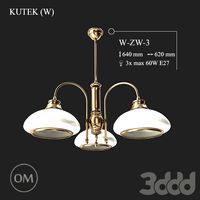
KUTEK (W) W-ZW-3
...kutek (w) w-zw-3
3ddd
kutek
3d модель люстри (w) w-zw-3 фабрики kutek. в архиве: max2012, obj, fbx, mat. (два варианта металла)
3ddd
$1
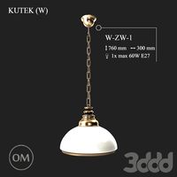
KUTEK (W) W-ZW-1
...kutek (w) w-zw-1
3ddd
kutek
3d модель люстри (w) w-zw-1 фабрики kutek. в архиве: max2012, obj, fbx, mat (два варианта металла).
3ddd
free
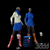
aneken W&W
...aneken w&w
3ddd
2 женских манекена, ценники и фолио. материалы и текстуры прилагаются.
design_connected
$9

KTribe W
...ktribe w
designconnected
ktribe w computer generated 3d model. designed by starck, philippe.
design_connected
$16

Troy W
...troy w
designconnected
magis troy w computer generated 3d model. designed by wanders, marcel.
turbosquid
$9

Menu - Benjamin Hubert - W W Carafe
... available on turbo squid, the world's leading provider of digital 3d models for visualization, films, television, and games.
turbosquid
$9

Menu - Benjamin Hubert - W W Carafe
... available on turbo squid, the world's leading provider of digital 3d models for visualization, films, television, and games.