Thingiverse

4BDN Jetboat hull
by Thingiverse
Last crawled date: 4 years, 2 months ago
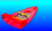
This is my latest stepped hull, a work in progress. Lots of advantages come with the steps and specific tile orientations to affect boat handling behavior.
I'll be CNC routing a model and creating a mould from the model.
Stay tuned for updates.
14/1/2020 Printability!
I hate models that require use of support structures to print. However, after my updates I posted below I realised that the saved split finalised model wasn't from the latest render. Retracing my steps, I found that the render failed at a particular point, I suspect after I'd saved an stl in a different format program than openscad. doesn't seem to be any way around it. So I've printed a stern piece with some manual assistance near the holes above the jet unit. It's not great in that region but it's quite usable. Next time I'll add supports.
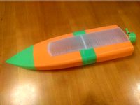
The Bow: I had planned to print it stern end up, bow pointing towards the heated bed. This looks great with support added up to 250 layers, I'm using 0.3mm per layer. So the whole thing appears quit printable, although a bit heavy in filament. I still have about 2.5 days of printing to complete it. I'll be sealing each section before assembly, still not sute if I'm going to use bitumen tape from my resin infusion supplies or glue or blue-tac
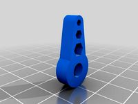
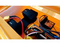
The 6 mini servo holes have a cable duct underneath and are general purpose except the two centre ones are reserved for steering and the option of a vertically trimmable steering nozzle mod. Plan is to fit the servos in with bluetack or power tack sealing all around the servo and cables in the servo mounting hole. Shouldn't be any need for screws, the steering load on my nozzle design is very minimal. Bottom two holes above the stator attaching point are for control rod boots. If you only use one then fill the other. Top two holes are for cooling water in from the stator and warmed water out from the ESC and motor. Don't lengthen the battery side motors or you will be wearing a sad face when the ESC caps blow.
12/1/2020. Been printing the stern. Found a region that didn't show in the 3D renders that prints so thin as to effectively be holes, either side of intake. Patched. Didn't like the chances of a nice print inside the transom where the coolant tubes and control rod boots attach so I went back in my openscad programs and thickened, added a mid bridging support flange and just covered the holes on the inside of the transom so the bridging won't be interrupted. Did a quick check of a 5mm shaft in the intake bearing housing, found my 5.4mm oversized hole slightly touches, be sure to add a bit of grease so the PLA doesn't turn into a hot-mess.
Added bottom support for the motor flange as this is the region that will take the most stress. Corrected the motor fixing hole spacing from 15mm between centres to 25mm between centres. Thinned the shroud that acts as a spray reducer.
re-rendered each step and made a fresh 3-segment model which can be split in a slicer.
Note that the bow section is printed stern end down, may need to watch layer height as it builds outward quite fast but should be achievable.
Also note that many popular slicers falsify the popup notes for computed nozzle width vs actual, the % setting bases not on actual nozzle width, but on layer height. Causing a lot of people to get non waterproof prints!
Later on 11/1/2019. Fitted the motor flange, the bearing holder and a trial water deflector.
Subtracted 2 x 0.01mm thick planes to section it into 3 pieces. Now it should be printable.
There is a cone between the jet unit shaft stub and the motor flange that is to make the printing nice, it should be cut off after so a universal joint can be fitted. No kiteboarding today :( was too wrapped up I finishing this!
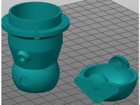
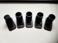
Created 0.01mm shear planes, divided boat into 3 sections. Loaded to slicer, separated the 3 sections, oriented each for printing and saved them. Added here, also with one of my stators(what restarted all this designing) and 4 steering nozzles. Bearings need to be 13mm OD, 5mm shaft, ceramic. There is a 10mm tube stub front of the intake bearing collar for a grease seal.
11/1/2019: Tried fitting a free stator design(FJD) but neither freecad or opencad were allowing the union operation. So I knocked up an intake tube of my own and fitted it, no dramas.
Now I've got to create and fit the shaft tube with bearing holes and the motor mount.
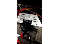
8/1/2020: Created voids for up to 5 x hobbyking Rhino 5 amp hour 50C 3S LiPo batteries, a 150 amp water cooled ESC, up to 4 mini servos, an FJD intake and a grunty 1700kv motor.
Also created internal holes and nut fitment pockets for SS Threaded rod fitting to tension 3D printed parts for additional support, now looking seriously at 3D printing this in parts. I've also constrained the outer dimensions of the hull: "resize([280,650,100])" which will let me print it in segments diagonally in my FLSUN cube printer.
17/12/2019: Switched out original hull with "fluidity 4BDN Hull.scad" with slightly changed stator cavity and with an intake pad to simplify jet unit mounting. There is a 3 degree downward tilt for both intake and stator.
I'll also be updating here:https://www.rcgroups.com/forums/showthread.php?3483031-4BDN-hull
And there are some stators I've designed here:https://www.rcgroups.com/forums/showthread.php?3441451-4BDN-FJD-35mm-stator-alternative
(These fit to the FJD inlet and impellors on the same forum.)
I'll be CNC routing a model and creating a mould from the model.
Stay tuned for updates.
14/1/2020 Printability!
I hate models that require use of support structures to print. However, after my updates I posted below I realised that the saved split finalised model wasn't from the latest render. Retracing my steps, I found that the render failed at a particular point, I suspect after I'd saved an stl in a different format program than openscad. doesn't seem to be any way around it. So I've printed a stern piece with some manual assistance near the holes above the jet unit. It's not great in that region but it's quite usable. Next time I'll add supports.
The Bow: I had planned to print it stern end up, bow pointing towards the heated bed. This looks great with support added up to 250 layers, I'm using 0.3mm per layer. So the whole thing appears quit printable, although a bit heavy in filament. I still have about 2.5 days of printing to complete it. I'll be sealing each section before assembly, still not sute if I'm going to use bitumen tape from my resin infusion supplies or glue or blue-tac
The 6 mini servo holes have a cable duct underneath and are general purpose except the two centre ones are reserved for steering and the option of a vertically trimmable steering nozzle mod. Plan is to fit the servos in with bluetack or power tack sealing all around the servo and cables in the servo mounting hole. Shouldn't be any need for screws, the steering load on my nozzle design is very minimal. Bottom two holes above the stator attaching point are for control rod boots. If you only use one then fill the other. Top two holes are for cooling water in from the stator and warmed water out from the ESC and motor. Don't lengthen the battery side motors or you will be wearing a sad face when the ESC caps blow.
12/1/2020. Been printing the stern. Found a region that didn't show in the 3D renders that prints so thin as to effectively be holes, either side of intake. Patched. Didn't like the chances of a nice print inside the transom where the coolant tubes and control rod boots attach so I went back in my openscad programs and thickened, added a mid bridging support flange and just covered the holes on the inside of the transom so the bridging won't be interrupted. Did a quick check of a 5mm shaft in the intake bearing housing, found my 5.4mm oversized hole slightly touches, be sure to add a bit of grease so the PLA doesn't turn into a hot-mess.
Added bottom support for the motor flange as this is the region that will take the most stress. Corrected the motor fixing hole spacing from 15mm between centres to 25mm between centres. Thinned the shroud that acts as a spray reducer.
re-rendered each step and made a fresh 3-segment model which can be split in a slicer.
Note that the bow section is printed stern end down, may need to watch layer height as it builds outward quite fast but should be achievable.
Also note that many popular slicers falsify the popup notes for computed nozzle width vs actual, the % setting bases not on actual nozzle width, but on layer height. Causing a lot of people to get non waterproof prints!
Later on 11/1/2019. Fitted the motor flange, the bearing holder and a trial water deflector.
Subtracted 2 x 0.01mm thick planes to section it into 3 pieces. Now it should be printable.
There is a cone between the jet unit shaft stub and the motor flange that is to make the printing nice, it should be cut off after so a universal joint can be fitted. No kiteboarding today :( was too wrapped up I finishing this!
Created 0.01mm shear planes, divided boat into 3 sections. Loaded to slicer, separated the 3 sections, oriented each for printing and saved them. Added here, also with one of my stators(what restarted all this designing) and 4 steering nozzles. Bearings need to be 13mm OD, 5mm shaft, ceramic. There is a 10mm tube stub front of the intake bearing collar for a grease seal.
11/1/2019: Tried fitting a free stator design(FJD) but neither freecad or opencad were allowing the union operation. So I knocked up an intake tube of my own and fitted it, no dramas.
Now I've got to create and fit the shaft tube with bearing holes and the motor mount.
8/1/2020: Created voids for up to 5 x hobbyking Rhino 5 amp hour 50C 3S LiPo batteries, a 150 amp water cooled ESC, up to 4 mini servos, an FJD intake and a grunty 1700kv motor.
Also created internal holes and nut fitment pockets for SS Threaded rod fitting to tension 3D printed parts for additional support, now looking seriously at 3D printing this in parts. I've also constrained the outer dimensions of the hull: "resize([280,650,100])" which will let me print it in segments diagonally in my FLSUN cube printer.
17/12/2019: Switched out original hull with "fluidity 4BDN Hull.scad" with slightly changed stator cavity and with an intake pad to simplify jet unit mounting. There is a 3 degree downward tilt for both intake and stator.
I'll also be updating here:https://www.rcgroups.com/forums/showthread.php?3483031-4BDN-hull
And there are some stators I've designed here:https://www.rcgroups.com/forums/showthread.php?3441451-4BDN-FJD-35mm-stator-alternative
(These fit to the FJD inlet and impellors on the same forum.)
Similar models
thingiverse
free
4BDN jetunit stators and nozzles for 35mm impellor
...earing and a 10mm outer diameter grease seal, a 5mm stainless steel shaft.
if you download, please throw a ~like~ on the page :-)
thingiverse
free

Modified hull section for 80% utility ship by buhatkj
... this part is in 80% scale, so you would want to scale it up to 125% if you are doing a full size version of peter's rc boat.
thingiverse
free

Modified files for easier construction by chickey
...t can steer easier.
i've put up a second remix that modified mounting holes for the motor so all four screws can be attached.
thingiverse
free

Motor shaft support (X) by michaeldaushh
...s well with a little bit pressure on the outer bearing ring.
-> installation without tension on the belt.
i printed it in pla.
thingiverse
free
OpenRC Tractor - Motor part 12a - alternative when using standard servo for steering by Renngarage
...nfortunately, the right "engine part" doesn't fit anymore, because of the servo. so i made a cutout in this part...
thingiverse
free
Hole-Shaft Fit Characterization Model by dvanommen
... shaft for a tight press fit. i've provided the solidworks file for you as well so you can change the hole sizes if you want.
thingiverse
free

F-120 Frigate Stern
...ize you require , scale to 100% uniform for a 6 to 7 foot long model that be made rc
please follow teddya27 for the files also
thingiverse
free

Kia Optima Steering Wheel Phone Holder **FOR USE ONLY WHILST PARKED**
...parked up.
i would also recommend printing in a bright colour so you won't forget it is there and drive off with it in place!
thingiverse
free
Servo attachment - For Nema 14 Stepper Motor by AnetA24U
... up the hole for the stepper shaft to fit. use a screw with a 4-5mm head and 5mm in length to tighten the stepper motor in place.
thingiverse
free

Wind-up Bathtub Boat V5 MOD - Hull in two peaces
...c delta print bed.
therefore i have split the model into two sections.
to make the glueup easier i have added holes for filapins.
Jetboat
3d_export
$10
DJCK Speedboat 3D Model
...djck speedboat 3d model 3dexport jetboat generic fast water turbine djck speedboat 3d model djcrazykorry...
thingiverse
free

Jetboat edited for cr-10 print size by Limpet65
...nce i cut the nose off in the solid part of the boat making sure to keep the slope on the hull to reduce any potential overhangs.
thingiverse
free
NQD Tear Into JetBoat Battery Holder by aliveathome
...le-sided tape to the bottom of the hull. use velcro-straps to secure the battery. use adhesive velcro to secure receiver and esc.
thingiverse
free

Jetboat shell and nozzle mods by eShaman
...iver aliexpress
as an addition wanna try fpv just for fun:
akk a3 aio camera
eachine rotg01 pro (otg on android)
vr box for phone
thingiverse
free

NQD Jetboat Impeller by Benm96
...d shaft. i printed in pla with supports (low density). abs or nylon may be more successful. if you try please share your results.
thingiverse
free
4BDN jetunit stators and nozzles for 35mm impellor
...the tip for efficient operation. i'm working on a jetboat hull here: https://www.thingiverse.com/thing:4051537 which i've built a compatible intake...
blendswap
free

Roughnecks Starship Troopers Jetboat
...ously released.you can see other models i've made and intend to release on my deviantart page (http://bcampo.deviantart.com/)
thingiverse
free

3D printed Jetsprint jetboat by JothamB
... i know many people still use thingiverse so here's the link:
https://www.youmagine.com/designs/prototype-jetsprint-jet-boat
thingiverse
free
Jetboat by georgdoll
...pte&t=209s
yet another scaled up rebuild : https://www.youtube.com/watch?v=ii5pzeeofo0
cool to see the design beeing used :)
Hull
3d_ocean
$12
Gauge Shell with Ammunition Components
...ammunition brenneke gauge shell high poly high resolution high-poly hull shell case primer shots slug wad 3d model of...
3d_ocean
$19
Olifant Mk1B Main Battle Tank - South Africa
...the tank. all meshes are linked to the main hull while the gun is linked to the...
3d_ocean
$15
Age of Sail_Caravel
...for trade. low poly game model, only 613 tris. hull & sail materials, 2048×2048 diffuse & normal maps.if you...
3d_ocean
$30

Millennium Falcon
...is basically texured with a metal material for the hull glass for the cockpit and an engine glow. the...
3d_ocean
$15

Airplane Hull
... high quality, low polygonal model, tileable, easy to tile into a bigger model. - poly count: 2580 - formats: max /obj /fbx/3d...
3ddd
$1

Split Sofa and Chair by Alex Hull
...ординаты текстур развернуты, модель готова к просчету.
общее количество полигонов - 64108.
форматы сцены в fbx и obj прилагаются.
3ddd
$1

Hull Furniture
...точки:
textures can be downloaded:http://3ddd.ru/3dmodels/show/parkiet_barlinek_dub_3_vida_multitexture_floorgenerator
3ddd
$1
Барный стул Industry Hull
...барный стул industry hull
3ddd
барный
высота (см): 55-81
ширина (см): 41
глубина (см): 41
cg_studio
$79
Char B13d model
...b1 heavy model 3d perspectx military gun tank self-propelled hull de bataille battle figther infantry arm .3ds .c4d .fbx...
3d_export
$80
Icebreaker 3D Model
...3dexport icebreaker ice breaker boat ship icebreaking ships commercial hull propeller helicopter helipad pod icebreaker 3d model tartino 4275...