Thingiverse
3DLS The Full Belt Free Printer From Morninglion Industries
by Thingiverse
Last crawled date: 4 years, 2 months ago
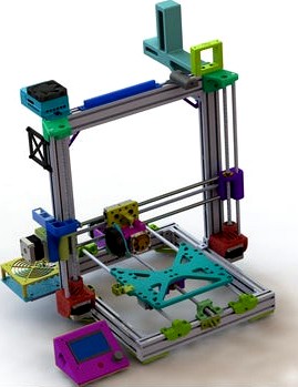
Welcome to the 3DLS Lead Screw Drive
Aluminum Frame 3D Printer
by MorningLion Industries!
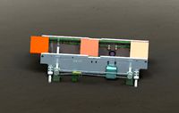
Here's a 4k render of the machine
Current Status:
I am writing the instructions now!
Printing at 80mm/sec with accel set to 300 on X and Y.
The precision is so good that the little compensations done by Prusa Slicer get printed out instead of compensating for anything.
Machine is done. Marlin 2.0.3 included. Requires SKR 1.3 to meet speed requirements and SKR 1.4 Turbo is highly recommended.
Machine runs best with LV8729 drivers. This is after testing TMC2208, TMC2130, and DRV8825. The LV offers the fastest stepping speed and a high amps capability supporting the larger motors on X and Y no problems.
Here's some pictures and links:
Slicer Settings, Prusa Slicer
It's now at 300 Accel X and Y with 100mm/sec top speed. There's still some over extrusion in the corners and some following of the infill. I am going to set infill/edge overlap to 0.
A video of it running for noise levels
The frame is based on Pheneeny's great AM8
The extrusions used are the same as theirs but that's it.
Everything except the frame is my design.
You can retrofit most of this back onto an AM8 bit by bit however there's a lot of tweaks here.
Specs:
Prusa Type 3D Printer with No Belts!
235x235x235 Build Area but this is scalable to larger.
Heated Bed, Uses Ender3 Bed
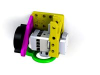
CR-10, Chimera Dual or E3D Extruder
Smooth Rails
Single or Dual Extruder
SKR 1.4 Turbo 32bit Control @ 120MHZ
LV8729 Drivers
Optional Full Web Control Via Octoprint Onboard
Many More Options and Accessories!
Goals:
Ultimate precision at an obtainable budget
High speed ability
Compact overall size for Cartesian machine
Off the shelf parts
Easiest possible assembly
No special tools or machining
Ultimate reliability, thousands of hours between service
The Things That This Is Inspired From:
In no particular order either....
AM8 Z Motor Mount and Top Mounts with Bearings On Both Ends!
AM8 Mod Y Rod Support wIth Full A8 Travel
Anet AM8 Y Axis Lead Screw Drive System
Anet A8 X Axis Lead Screw Drive System
Creality CR-10 & Ender3 Type Extruder Mount for Anet A8 and Alike!
AM8, Creality and Other 2020 Series Printer Rear or Side Spool Holder
2020 Series Extruder Mounting Clamp
8mm Frame or 2020 Bowden Inlet with Filament Sensor
SKR 1.3 Multi-Mount! Fits 92 or 80mm Fan
2020 Series Frame Raspberry Pi 2 & 3 Case Mount with 60mm Fan - Octoprint Ready!
2 Place 2040 Terminal Block
2020 Series Frame Raspberry Pi Camera Mount
Lion Link Narrow Y axis chain for AM8 mod!
Simple 2020 RAMPS and 80mm Fan Mount
Quaq MOSFET 2020 Mount
2020 to 8mm Frame Adapter for Accessories!
These have been used as is or modified and assembled here into a standalone Cartesian 3D Printer with No Belts!
BOM:
Items that are direct links are the parts the machine is designed to fit.
380mm Smooth Rods x 4
436mm Smooth Rods x 2 for X
SC8UU Bearing Holders x 7
LM8UU Bearings x 7 I like Drylin here.
340mm 2040 Extrusion x 2
313mm 2050 Extrusion x 3
440mm Extrusion x 2
2020 Series Metal Corner Brackets x 12
M5x10mm Button Head Socket Cap Screw just buy the 100 pack
M5 2020 Series T Nut also get the 100 pack, These simplify the assembly so much! You can easily slide fasteners in.
15 Amp 24 Volt Power Supply of Good Quality
XT60 Connector
12AWG Silicone Wire in Red and Black, about 10 feet works good.
Hotend of your choice, I included mounts for the stock type, an E3D Bowden or the CR-10 hotends.
BLTouch is recommended
SKR 1.4 Turbo board
LV8729 Drivers
Raspberry pi 3B+ for Octoprint
4 way MOSFET board for Octoprint GPIO Control
12v 40amp Relay for Octoprint
A Metric Screw Assortment, you're gonna need em.
3 X NEMA17 Steppers like these
2 X NEMA 17 Steppers with High Torque like these for X and Y axis.
Your favorite extruder, I like this one
Endstops like these
Rubber Feet like these
400mm Lead Screw with Anti-Backlash Nut
Couplers x 2 for X and Y
Flex Couplers for Z Axis
608RS Bearings X6
Locking Collars x 4
688-2RS-BU Bearings x 2
400mm long 8mm 4 start lead screw with Anti-Backlash nut
12864 RepRap Discount Full Graphic LCD case is included.
Creality Ender3 Heated Bed
Glass for Ender3 bed
Adhesive Sheet for Bed Glass
Bed Screws Kit
24v to 12v converter Module
24v to 5v Converter Module
Why the SKR 1.4 Turbo?
It's all about speed with lead screws. The speed a stepper can run at on a controller is proportional to the CPU speed. The CPU is what generates the pulses required to run the motor.
As an example a RAMPS with Arduino MEGA 2560 runs at 16 MHZ. This limits the step generation to about 10MHZ before the CPU gets bogged down and begins to miss steps, this is with a single stepper too, divide that across 4 and you can quickly run into issues. This is with Marlin FW.
Now on a board with a faster CPU like a SKR 1.4 Turbo at 120MHZ can run the steppers up to 100MHZ pretty easily. This means a much higher top speed without bogging the CPU down and causing issues. Also the 32bit board has much more RAM for running Marlin effectively.
Now there's still other considerations for speed and this machine will never be quiet. It's not meant to be fast or silent though you are trading those in for a much more precise control and quality in the print. As it sits I am limiting speeds to 100mm/sec at quad stepping in X and Y. Since the screw has to turn 4x faster for the same speed compared to the belt this runs it at the same steps per mm as the belt since it's 1/4th less steps.
This has no real effect on accuracy. It's all about elimination lash and the rubber band effect all belts have. I have run a tolerance test at 60mm/sec print speed with this machine and got .2mm pass on it. On my highly tuned Anet A8 I ran the same test at 40mm/sec and got .3mm.
There's more info on the SKR 1.4 Turbo here and this page has lots of information on stepper driving and speeds here.
Assembly!
First cut the extrusions or you can find pre-cut kits for the AM8 on Ebay. You need 340mm long x2, 313mm x 3 and 440mm x 2. the ends of the 440mm sections should be tapped to M5, the holes are already sized and I like to use a tap drill for this.For now you can get the AM8 build guide or reference my renders and photos. I am still working ona proper guide.
Use the 3D printed frame corners to assemble the printer loosely first. just barely hand snug the bolts. The If you use the T-nuts you can pre-load the part and put the nuts in the channel then tighten.
Secure the corners with metal corner brackets on the insides. Tighten snug all the bolts on the printed pieces. Fully assemble the frame at this point.
For the Y axis mount the motor then coupler and bearing. Cap the bearing then slide the 8mm lead screw through the bearing into the joint on the motor and tighten. Install the Y axis nut in the holder and gently work it down the Y axis lead screw a good 100mm. Install a Collar Spacer and lock collar on the other end of the rod and slide the bearing holder on next. Keep this collar loose for now.
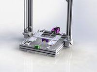
Install the 4 sliding bearings for the bed on the Y axis carriage with the nut adapter and chain mount.
Mount the Y rods and holders loosely, then mount the Y motor mount and front bearing support. Push the lead screw towards the motor and tighten the locking collar up against the collar spacer and bearing.
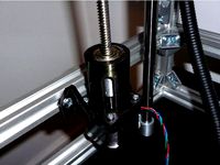
Mount the flex couplers on the Z motor and the bearing in the mount. Install the Z lead screw and slide it all up into the bottom Z motor mount and mount loose on frame.
Setup the X axis. Install the LM8UU bearings in the holders and mount the lead screw nuts on both. Install the lead screw bearings and cap. Mount the motor then install the motor coupler. Slide the lead screw in through a collar spacer and lock collar. Push the rod firmly into the coupler and slide the lock collar up to the spacer and bearing and tighten then tighten the coupler.
Install the X axis nut on the carriage part and then on the lead screw.
Setup install the left side first by easing it down the Z lead screw. Then install the right side mounting the X lead screw in the bearing and working it down the right Z lead screw.
Mount the bearings in the Z upper caps and secure with the covers. Install the upper Z mounts sliding the lead screw into the upper bearing. Loosely attach the upper mounts to the frame then slide the smooth rod down through the top then the X carriages and finally into the lower mounts. Set the distance by sliding the lower mounts down and cap the smooth rods into the upper. Then tighten the upper mounts to the frame and push the lowers up capturing the smooth rod between them and tighten. The upper mounts should be even with the top of the upright frame.
Mount the Y axis nut support on the Y bed frame then mount the frame on the Y bearings while sliding the nut holder of the lead screw into the mount on the bed frame.
Wiring
It's best to start by mounting the SKR, voltage converters, wiring block, MOSFETs board, RPi, and any meters you choose to include.
Start at the power supply. Wire 24v from the power supply to each voltage converter.
Run 5v to the RPi
Run 12v to the MOSFET board input. From there go to your lights, accessories and the relay for main power.
Negative from the power supply goes right to the SKR. The positive goes to the large relay and out to the SKR from the NO terminal.
Endtops, motors and others simply follow their directions.
Firmware Notes!
I use Marlin 2.0.3 on a SKR 1.4 board. This is a 32bit board. I also use LV8729 drivers for maximum reliability at the high stepping speeds required.
To use these you want the jumpers on the SKR for Y and X axis to be #2 closed, the rest removed. For Z and E you want #3 closed and the rest removed, This sets X and Y to 1/4 steps and E and Z to 1/16th steps.
Set driver current voltages to 0.95V on X and Y and 0.75v on E and Z.
Now for the longer travel in the Y axis you will need to setup your home offsets and positions. Use these instructions to set home offsets. What I do is send command G0 X0 Y0 and adjust these offsets until the nozzle is over the corner of the bed. Make you adjustment and send the command again, save with M500.
In the firmware archive there's a Firmware folder with the files you need to copy into your Marlin folder then adjust and compile. It's set to SKR1.3 board with LV8729 by default.
If you wanna help me make these builds and others, as well as the sweet renders and buying machine parts, consider a donation! Maybe I will save them up towards replacing my 8 year old computer. You can always contact me a via a PM as well.
Thank you!
Aluminum Frame 3D Printer
by MorningLion Industries!
Here's a 4k render of the machine
Current Status:
I am writing the instructions now!
Printing at 80mm/sec with accel set to 300 on X and Y.
The precision is so good that the little compensations done by Prusa Slicer get printed out instead of compensating for anything.
Machine is done. Marlin 2.0.3 included. Requires SKR 1.3 to meet speed requirements and SKR 1.4 Turbo is highly recommended.
Machine runs best with LV8729 drivers. This is after testing TMC2208, TMC2130, and DRV8825. The LV offers the fastest stepping speed and a high amps capability supporting the larger motors on X and Y no problems.
Here's some pictures and links:
Slicer Settings, Prusa Slicer
It's now at 300 Accel X and Y with 100mm/sec top speed. There's still some over extrusion in the corners and some following of the infill. I am going to set infill/edge overlap to 0.
A video of it running for noise levels
The frame is based on Pheneeny's great AM8
The extrusions used are the same as theirs but that's it.
Everything except the frame is my design.
You can retrofit most of this back onto an AM8 bit by bit however there's a lot of tweaks here.
Specs:
Prusa Type 3D Printer with No Belts!
235x235x235 Build Area but this is scalable to larger.
Heated Bed, Uses Ender3 Bed
CR-10, Chimera Dual or E3D Extruder
Smooth Rails
Single or Dual Extruder
SKR 1.4 Turbo 32bit Control @ 120MHZ
LV8729 Drivers
Optional Full Web Control Via Octoprint Onboard
Many More Options and Accessories!
Goals:
Ultimate precision at an obtainable budget
High speed ability
Compact overall size for Cartesian machine
Off the shelf parts
Easiest possible assembly
No special tools or machining
Ultimate reliability, thousands of hours between service
The Things That This Is Inspired From:
In no particular order either....
AM8 Z Motor Mount and Top Mounts with Bearings On Both Ends!
AM8 Mod Y Rod Support wIth Full A8 Travel
Anet AM8 Y Axis Lead Screw Drive System
Anet A8 X Axis Lead Screw Drive System
Creality CR-10 & Ender3 Type Extruder Mount for Anet A8 and Alike!
AM8, Creality and Other 2020 Series Printer Rear or Side Spool Holder
2020 Series Extruder Mounting Clamp
8mm Frame or 2020 Bowden Inlet with Filament Sensor
SKR 1.3 Multi-Mount! Fits 92 or 80mm Fan
2020 Series Frame Raspberry Pi 2 & 3 Case Mount with 60mm Fan - Octoprint Ready!
2 Place 2040 Terminal Block
2020 Series Frame Raspberry Pi Camera Mount
Lion Link Narrow Y axis chain for AM8 mod!
Simple 2020 RAMPS and 80mm Fan Mount
Quaq MOSFET 2020 Mount
2020 to 8mm Frame Adapter for Accessories!
These have been used as is or modified and assembled here into a standalone Cartesian 3D Printer with No Belts!
BOM:
Items that are direct links are the parts the machine is designed to fit.
380mm Smooth Rods x 4
436mm Smooth Rods x 2 for X
SC8UU Bearing Holders x 7
LM8UU Bearings x 7 I like Drylin here.
340mm 2040 Extrusion x 2
313mm 2050 Extrusion x 3
440mm Extrusion x 2
2020 Series Metal Corner Brackets x 12
M5x10mm Button Head Socket Cap Screw just buy the 100 pack
M5 2020 Series T Nut also get the 100 pack, These simplify the assembly so much! You can easily slide fasteners in.
15 Amp 24 Volt Power Supply of Good Quality
XT60 Connector
12AWG Silicone Wire in Red and Black, about 10 feet works good.
Hotend of your choice, I included mounts for the stock type, an E3D Bowden or the CR-10 hotends.
BLTouch is recommended
SKR 1.4 Turbo board
LV8729 Drivers
Raspberry pi 3B+ for Octoprint
4 way MOSFET board for Octoprint GPIO Control
12v 40amp Relay for Octoprint
A Metric Screw Assortment, you're gonna need em.
3 X NEMA17 Steppers like these
2 X NEMA 17 Steppers with High Torque like these for X and Y axis.
Your favorite extruder, I like this one
Endstops like these
Rubber Feet like these
400mm Lead Screw with Anti-Backlash Nut
Couplers x 2 for X and Y
Flex Couplers for Z Axis
608RS Bearings X6
Locking Collars x 4
688-2RS-BU Bearings x 2
400mm long 8mm 4 start lead screw with Anti-Backlash nut
12864 RepRap Discount Full Graphic LCD case is included.
Creality Ender3 Heated Bed
Glass for Ender3 bed
Adhesive Sheet for Bed Glass
Bed Screws Kit
24v to 12v converter Module
24v to 5v Converter Module
Why the SKR 1.4 Turbo?
It's all about speed with lead screws. The speed a stepper can run at on a controller is proportional to the CPU speed. The CPU is what generates the pulses required to run the motor.
As an example a RAMPS with Arduino MEGA 2560 runs at 16 MHZ. This limits the step generation to about 10MHZ before the CPU gets bogged down and begins to miss steps, this is with a single stepper too, divide that across 4 and you can quickly run into issues. This is with Marlin FW.
Now on a board with a faster CPU like a SKR 1.4 Turbo at 120MHZ can run the steppers up to 100MHZ pretty easily. This means a much higher top speed without bogging the CPU down and causing issues. Also the 32bit board has much more RAM for running Marlin effectively.
Now there's still other considerations for speed and this machine will never be quiet. It's not meant to be fast or silent though you are trading those in for a much more precise control and quality in the print. As it sits I am limiting speeds to 100mm/sec at quad stepping in X and Y. Since the screw has to turn 4x faster for the same speed compared to the belt this runs it at the same steps per mm as the belt since it's 1/4th less steps.
This has no real effect on accuracy. It's all about elimination lash and the rubber band effect all belts have. I have run a tolerance test at 60mm/sec print speed with this machine and got .2mm pass on it. On my highly tuned Anet A8 I ran the same test at 40mm/sec and got .3mm.
There's more info on the SKR 1.4 Turbo here and this page has lots of information on stepper driving and speeds here.
Assembly!
First cut the extrusions or you can find pre-cut kits for the AM8 on Ebay. You need 340mm long x2, 313mm x 3 and 440mm x 2. the ends of the 440mm sections should be tapped to M5, the holes are already sized and I like to use a tap drill for this.For now you can get the AM8 build guide or reference my renders and photos. I am still working ona proper guide.
Use the 3D printed frame corners to assemble the printer loosely first. just barely hand snug the bolts. The If you use the T-nuts you can pre-load the part and put the nuts in the channel then tighten.
Secure the corners with metal corner brackets on the insides. Tighten snug all the bolts on the printed pieces. Fully assemble the frame at this point.
For the Y axis mount the motor then coupler and bearing. Cap the bearing then slide the 8mm lead screw through the bearing into the joint on the motor and tighten. Install the Y axis nut in the holder and gently work it down the Y axis lead screw a good 100mm. Install a Collar Spacer and lock collar on the other end of the rod and slide the bearing holder on next. Keep this collar loose for now.
Install the 4 sliding bearings for the bed on the Y axis carriage with the nut adapter and chain mount.
Mount the Y rods and holders loosely, then mount the Y motor mount and front bearing support. Push the lead screw towards the motor and tighten the locking collar up against the collar spacer and bearing.
Mount the flex couplers on the Z motor and the bearing in the mount. Install the Z lead screw and slide it all up into the bottom Z motor mount and mount loose on frame.
Setup the X axis. Install the LM8UU bearings in the holders and mount the lead screw nuts on both. Install the lead screw bearings and cap. Mount the motor then install the motor coupler. Slide the lead screw in through a collar spacer and lock collar. Push the rod firmly into the coupler and slide the lock collar up to the spacer and bearing and tighten then tighten the coupler.
Install the X axis nut on the carriage part and then on the lead screw.
Setup install the left side first by easing it down the Z lead screw. Then install the right side mounting the X lead screw in the bearing and working it down the right Z lead screw.
Mount the bearings in the Z upper caps and secure with the covers. Install the upper Z mounts sliding the lead screw into the upper bearing. Loosely attach the upper mounts to the frame then slide the smooth rod down through the top then the X carriages and finally into the lower mounts. Set the distance by sliding the lower mounts down and cap the smooth rods into the upper. Then tighten the upper mounts to the frame and push the lowers up capturing the smooth rod between them and tighten. The upper mounts should be even with the top of the upright frame.
Mount the Y axis nut support on the Y bed frame then mount the frame on the Y bearings while sliding the nut holder of the lead screw into the mount on the bed frame.
Wiring
It's best to start by mounting the SKR, voltage converters, wiring block, MOSFETs board, RPi, and any meters you choose to include.
Start at the power supply. Wire 24v from the power supply to each voltage converter.
Run 5v to the RPi
Run 12v to the MOSFET board input. From there go to your lights, accessories and the relay for main power.
Negative from the power supply goes right to the SKR. The positive goes to the large relay and out to the SKR from the NO terminal.
Endtops, motors and others simply follow their directions.
Firmware Notes!
I use Marlin 2.0.3 on a SKR 1.4 board. This is a 32bit board. I also use LV8729 drivers for maximum reliability at the high stepping speeds required.
To use these you want the jumpers on the SKR for Y and X axis to be #2 closed, the rest removed. For Z and E you want #3 closed and the rest removed, This sets X and Y to 1/4 steps and E and Z to 1/16th steps.
Set driver current voltages to 0.95V on X and Y and 0.75v on E and Z.
Now for the longer travel in the Y axis you will need to setup your home offsets and positions. Use these instructions to set home offsets. What I do is send command G0 X0 Y0 and adjust these offsets until the nozzle is over the corner of the bed. Make you adjustment and send the command again, save with M500.
In the firmware archive there's a Firmware folder with the files you need to copy into your Marlin folder then adjust and compile. It's set to SKR1.3 board with LV8729 by default.
If you wanna help me make these builds and others, as well as the sweet renders and buying machine parts, consider a donation! Maybe I will save them up towards replacing my 8 year old computer. You can always contact me a via a PM as well.
Thank you!
Similar models
thingiverse
free

AM8 Z Motor Mount and Top Mounts with Bearings On Both Ends!
...ading or really any m3 screw to attach.
i use m5 x 10 screws and t nuts for my am8 so these will fit that for sure.
thank you!
thingiverse
free
Anet AM8 Y Axis Lead Screw Drive System
...achine you wont believe was once an anet a8!
thank you!
update 12/6/19 all files reloaded and ready to go! released to the wild.
thingiverse
free
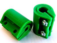
5mm to 8mm Z axis shaft coupler by mrice
...ible shaft couplers on z axis rods, for 5mm motor shafts and 8mm threaded rods. use two m3x10mm screws and nuts to tighten down.
thingiverse
free
Hypercube Bearing Supported Z Axis Leadscrew Motor Mount by butchja
...g furthermore.
doublecheck your mounting direction before printing. in contrast to the original design it is mounted in reverse.
thingiverse
free

I3 Mega z-axis leading
...d to print:
2 times main
1 time left
1 time right.
you also need 2x 608 bearings 2x m3x20 din912 screws and 2x m3 din934 hex nuts
thingiverse
free

Prusa i3 Mk3 Bearing Z Axis Top Mount by jlnevill
...he lead screws then check that the z axis stepper motor mounts are square to the frame.
this design requires two 608 bearings.
thingiverse
free
AM8 - 200x300 buildplate - 350mm Z height by bipsen
...h additional material added for better strength (i saw some like these somewhere - but cannot remember if it was on thingiverse).
thingiverse
free

AM8 Rods Holder Z-AXIS with bearing by mamsih99
.....
you can hold the bearing with screw of m3 if there little playing in the bearing holder
for me it was nice fit so ..
good luck
thingiverse
free
Z-Axis Lead Screw Nut Linear Bearing Mount by virtualight
...lead screw nut linear bearing mount by virtualight
thingiverse
prototype z-axis lead screw nut linear bearing mount for rigidbot
thingiverse
free

Ender Z Axis Motor Mount Long Holes by GrafKnusprig
...-axis a few times so that the motor finds its optimal position. then tighten the screws and check the spindle for smooth running.
Morninglion
thingiverse
free

Morninglion Industries 3DLS by fluxcore
...morninglion industries 3dls by fluxcore
thingiverse
morninglion industries 3dls
thingiverse
free

MorningLion Industries X Connect Board PCB Files by morganlowe
... screw drive cr-10 s5.
i got mine from jlcpcb.com for about $16 total, for 5. get the dhl shipping, it's worth it!
thank you
thingiverse
free

Morninglion Industries BTT ZSYong Mount for CR & Ender Machines by morganlowe
...for cooling and a 50x15mm blower for part cooling. bltouch is optional but included.
the offset is +30mm in the x 0 y
thank you!
thingiverse
free
Morninglion Mount for BIQU H2 fits Crealtiy CR and Ender series plus others! BLTouch Option! by morganlowe
...bltouch fan mounting. the probe is -18.5x and -25.5y.
it mounts to the machine with the wheel bolts on the x carriage,
thank you!
thingiverse
free
Morninglion Mount for BIQU H2 fits 3DLS, Anet A8 and more! Optional BLTouch! by morganlowe
...qu h2 model i used this in the renders.
thank you!
any questions post them here or find me in the morninglion industries discord
thingiverse
free

Nintendo64 Inspired Raspberry PI Case by Morninglion Industries by morganlowe
...crews.
print with support, the lid is a complex shape and not easy to print!
this is roughly 50% original n64 size.
thank you!~
thingiverse
free

Morninglion Industries Raspberry Pi Case Mounted SSD Enclosure by morganlowe
...l stack! you can use the one with magnet holes and some 8x3mm magnets to give it a nice snap when putting it together.
thank you!
thingiverse
free

Ender3 & CR series X Axis Chain System by morganlowe
...use chain!. the x board mount is for my morninglion x axis connection board as an option. thanks to...
thingiverse
free

Smarthub Enclosure for Raspberry Pi Home Assistant Build with Official 7" RPi Touchscreen by morganlowe
...got questions you can find me and others at morninglion industries...
3Dls
thingiverse
free
Morninglion Industries 3DLS by fluxcore
...morninglion industries 3dls by fluxcore
thingiverse
morninglion industries 3dls
thingiverse
free

AM8 - 3DLS Gantry Position Tool by morganlowe
...am8 - 3dls gantry position tool by morganlowe
thingiverse
just a simple thing to set where the gantry should go!
thingiverse
free

Toggle Switch LED Project for 3DLS by OpenSourceClassroom
...ject that helps to exercise basic 3d literacy skills. 2 leds being controlled by a switch on the other side of the project board.
thingiverse
free

Bondtech Direct Drive for Ender3 Type Extruder on Anet A8 & 3DLS by morganlowe
...the nozzle, no y offset.
update 9/29/2020 updated the fan duct for much better performance and improved the 90 degree chain link.
renderosity
$11

Convert It! - Iray to 3DL Characters
...or limitations" section in product readme for important usage instructions and issues regarding transparency maps.</p>
thingiverse
free

Direct Drive Mod To Install Cr-10 or Ender3 Hotend on Anet A8 & 3DLS by morganlowe
...tes to come!
update 9/5/2020 completely redesigned it... every... last... part. much more compact and closer to the extruder now.
renderosity
$11

Swamp Tree
... environment.duf, 3dl cameras,<br />
3dl lighting, 3dl materials<br />
-iray set:iray material, iray render</p>
thingiverse
free
Morninglion Mount for BIQU H2 fits 3DLS, Anet A8 and more! Optional BLTouch! by morganlowe
...qu h2 model i used this in the renders.
thank you!
any questions post them here or find me in the morninglion industries discord
renderosity
$4

NYC Couture CatharinaG3
...format<br />
10 real world patterned styles in 3dl format<br />
<br />
4 metal styles in iray and 3dl</p>
renderosity
$25

Fantasy Street Market - SW
...;
add any products from your runtime to the market stalls if your character is looking to buy that something special ;)</p>
Belt
turbosquid
$9
Belt conveyor belt
...t conveyor belt for download as 3ds, ige, obj, stl, and sldas on turbosquid: 3d models for games, architecture, videos. (1226546)
3d_export
$6
belt
...d then comes off and fastens at the front of the seat. version: 2015 units: millimetres x-form: yes polys: 120 950 verts: 163 944
3d_export
$7
belt grinder
...belt grinder
3dexport
belt grinder
3d_export
$5
Belt conveyor
...belt conveyor
3dexport
belt conveyor
3ddd
$1
column belt
...column belt
3ddd
колонна
column belt
turbosquid
$5
Belt
... available on turbo squid, the world's leading provider of digital 3d models for visualization, films, television, and games.
3d_ocean
$5
Leather Belt
...ather belt is created in 3dsmax 2011 and rendered with vray 1.5 and it has all the texture included with the multiple obj format.
3d_ocean
$5
Belt Ring
...belt ring
3docean
belt jewelry ring
belt ring 3d model. total weight 3.5 gram & 1.1 stone size. 3dm and obj file format.
design_connected
$11
Belt Round
...belt round
designconnected
meridiani belt round computer generated 3d model. designed by parisio, andrea.
design_connected
$11
Belt Oval
...belt oval
designconnected
meridiani belt oval computer generated 3d model. designed by parisio, andrea.
Industries
design_connected
$13

Industrial
...industrial
designconnected
dreizehngrad industrial computer generated 3d model.
3ddd
free

Industrial chair
...industrial chair
3ddd
industrial
industrial chair
3d_export
$5
industrial furniture - industrial table 01
...industrial furniture - industrial table 01
3dexport
"industrial table 01"
3ddd
free
Industrial table
...дустриальный , кофейный , стол
industrial table
3ddd
$1

L-Industry
...l-industry
3ddd
l-industry
промышленные светильники l-industry . диаметр × высота 320х492мм
3d_export
$5

industrial machine
...industrial machine
3dexport
industrial machine
3d_export
$5

industrial oven
...industrial oven
3dexport
industrial oven
3d_export
$5
industrial wheel
...industrial wheel
3dexport
industrial wheel
3ddd
$1
REFLECTOR INDUSTRIAL
...reflector industrial
3ddd
reflector industrial
3ddd
$1
Industrial light
...industrial light
3ddd
grange
industrial light.
Full
3ddd
$1

Full Mobili
...ull mobili , шкаф
группа шкафов, серия мебели "классика" фабрики «full mobili»
turbosquid
$80
full man body+full facials
... available on turbo squid, the world's leading provider of digital 3d models for visualization, films, television, and games.
3ddd
$1
Full Mobili
...сика , стол
стол круглый офисный серия мебели "классика" фабрики «full mobili»
3ddd
$1
FULL MOBILI
... стол
cтол офисный серии мебели "классика" итальянской компании full mobili
design_connected
$16

Full Circle
...full circle
designconnected
atmosphere full circle computer generated 3d model.
3d_export
$5

full office
...full office
3dexport
this is full office cgi model created with maya -detailed -textured -uv mapped
design_connected
$16

Full Moon
...full moon
designconnected
roche bobois full moon computer generated 3d model. designed by ragot, cedric.
turbosquid
$100

FULL KITCHEN
...squid
royalty free 3d model full kitchen for download as skp on turbosquid: 3d models for games, architecture, videos. (1345817)
turbosquid
$15

Full Bedroomset
...id
royalty free 3d model full bedroomset for download as max on turbosquid: 3d models for games, architecture, videos. (1540649)
3d_export
$10
full human body
...full human body
3dexport
it is a full human sculpt
Printer
archibase_planet
free
Printer
...inter
archibase planet
printer laser printer pc equipment
printer n120614 - 3d model (*.gsm+*.3ds) for interior 3d visualization.
archibase_planet
free
Printer
...rchibase planet
laser printer office equipment computer equipment
printer - 3d model (*.gsm+*.3ds) for interior 3d visualization.
turbosquid
$100

Printer
...er
turbosquid
royalty free 3d model printer for download as on turbosquid: 3d models for games, architecture, videos. (1487819)
turbosquid
$3
Printer
...turbosquid
royalty free 3d model printer for download as max on turbosquid: 3d models for games, architecture, videos. (1670230)
turbosquid
$1
printer
...turbosquid
royalty free 3d model printer for download as max on turbosquid: 3d models for games, architecture, videos. (1595546)
turbosquid
$1
printer
...turbosquid
royalty free 3d model printer for download as max on turbosquid: 3d models for games, architecture, videos. (1595105)
turbosquid
$10

Printer
...id
royalty free 3d model printer for download as max and 3dm on turbosquid: 3d models for games, architecture, videos. (1607146)
turbosquid
$7
Printer
...royalty free 3d model printer for download as ma, ma, and obj on turbosquid: 3d models for games, architecture, videos. (1644580)
turbosquid
$30
Printer
... available on turbo squid, the world's leading provider of digital 3d models for visualization, films, television, and games.
turbosquid
$20
Printer
... available on turbo squid, the world's leading provider of digital 3d models for visualization, films, television, and games.
Free
design_connected
$13

Free
...free
designconnected
parri design free armchairs computer generated 3d model. designed by marco maran.
turbosquid
$5
free
... available on turbo squid, the world's leading provider of digital 3d models for visualization, films, television, and games.
turbosquid
$5

Free
... available on turbo squid, the world's leading provider of digital 3d models for visualization, films, television, and games.
turbosquid
free
Free
... available on turbo squid, the world's leading provider of digital 3d models for visualization, films, television, and games.
design_connected
free
Free barstool
...free barstool
designconnected
free 3d model of free barstool by kristalia designed by graffeo, monica.
3d_export
$5

free mixamo
...free mixamo
3dexport
free mixamo
3d_export
free

free rocks
...free rocks
3dexport
free price rock
turbosquid
free

Free Free Standing Punching Bag
... available on turbo squid, the world's leading provider of digital 3d models for visualization, films, television, and games.
turbosquid
free

character free
...urbosquid
free 3d model character free for download as blend on turbosquid: 3d models for games, architecture, videos. (1321193)
turbosquid
free

Hamburger Free
...urbosquid
free 3d model hamburger free for download as blend on turbosquid: 3d models for games, architecture, videos. (1592262)