Thingiverse
3D Printed ESP8622 Smart Switch Outlet by GuarddogTryker
by Thingiverse
Last crawled date: 3 years ago
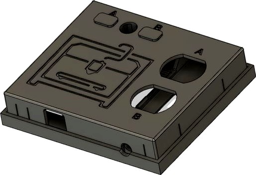
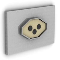
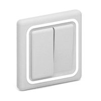
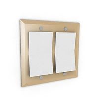
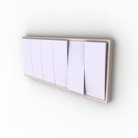
Included in this thing are the housing components for a smart switch I built to turn off and on my 3D printer remotely as I do not like to leave it running when I am away from home after it is done printing. The printer is monitored by security camera and can be turned off and on with the switch which fits within the housing.
Building this project "thing" requires some intermediate to advance knowledge of electronics (soldering, circuit design, modem configuration, ESP programming) and experience with wiring devices pulling household power. I will not go into great detail on how to build this because if you can not figure out how to assemble the components I list, then perhaps a store bought solution will be safer for you.
By downloading these components you agree that you fully understand that electricity is dangerous. And you, and only you, is responsible for your own safety and surroundings. You also agree I am not responsible for anything which may happen to you, those around you, or your property. If you are not properly trained or experienced working with household main power, then do not attempt this project.
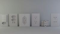
Components for which this box is designed to fit:
2 each: 3v Relay Board Power Switch Relay Module 1 Channel Optocoupler with Opto Isolation High Level Trigger
1 each: ESP8266 NodeMCU CP2102 ESP-12E Development Board (or any other controller which will fit on the perf board and has enough ports for the relays)
1 each: 3X7CM double-sided PCB board with 240 holes
4 each: 5mm leds (I used the clear version of red and green for off and on status)
2 each: 230 ohm 1/2 Watt resisters (or a value close to that for the leds)
2 each: 2.54mm Spacing Female 16 Pins PCB Header Connector Single Row (this is so you don't have to solder directly to the controller and so you can run wires between the ESP and the PCB board)
1 each: 4 Pin Tact Tactile Push Button Switch Momentary 12x12x7.3mm with Switch Cap
1 each: Standard USA 110V 2 plug wall outlet
1 each: 3 to 5 feet of 10 gauge 3 wire extension cord wire with male end attached
Links to videos concerning device:
https://www.reddit.com/r/3Dprinting/comments/ms8e4v/phase_1_completed_for_home_made_3d_printer_remote/?utm_source=share&utm_medium=ios_app&utm_name=iossmf
https://www.reddit.com/r/3Dprinting/comments/mtjpuz/phase_2_completed_for_home_made_3d_printer_remote/?utm_source=share&utm_medium=ios_app&utm_name=iossmf
https://www.reddit.com/r/3Dprinting/comments/mu5l83/pretty_much_done_with_3d_printed_home_made_smart/?utm_source=share&utm_medium=ios_app&utm_name=iossmf
https://www.reddit.com/r/3Dprinting/comments/mug9u4/3d_printer_smart_switch_project_finally_completed/?utm_source=share&utm_medium=ios_app&utm_name=iossmf
Building this project "thing" requires some intermediate to advance knowledge of electronics (soldering, circuit design, modem configuration, ESP programming) and experience with wiring devices pulling household power. I will not go into great detail on how to build this because if you can not figure out how to assemble the components I list, then perhaps a store bought solution will be safer for you.
By downloading these components you agree that you fully understand that electricity is dangerous. And you, and only you, is responsible for your own safety and surroundings. You also agree I am not responsible for anything which may happen to you, those around you, or your property. If you are not properly trained or experienced working with household main power, then do not attempt this project.
Components for which this box is designed to fit:
2 each: 3v Relay Board Power Switch Relay Module 1 Channel Optocoupler with Opto Isolation High Level Trigger
1 each: ESP8266 NodeMCU CP2102 ESP-12E Development Board (or any other controller which will fit on the perf board and has enough ports for the relays)
1 each: 3X7CM double-sided PCB board with 240 holes
4 each: 5mm leds (I used the clear version of red and green for off and on status)
2 each: 230 ohm 1/2 Watt resisters (or a value close to that for the leds)
2 each: 2.54mm Spacing Female 16 Pins PCB Header Connector Single Row (this is so you don't have to solder directly to the controller and so you can run wires between the ESP and the PCB board)
1 each: 4 Pin Tact Tactile Push Button Switch Momentary 12x12x7.3mm with Switch Cap
1 each: Standard USA 110V 2 plug wall outlet
1 each: 3 to 5 feet of 10 gauge 3 wire extension cord wire with male end attached
Links to videos concerning device:
https://www.reddit.com/r/3Dprinting/comments/ms8e4v/phase_1_completed_for_home_made_3d_printer_remote/?utm_source=share&utm_medium=ios_app&utm_name=iossmf
https://www.reddit.com/r/3Dprinting/comments/mtjpuz/phase_2_completed_for_home_made_3d_printer_remote/?utm_source=share&utm_medium=ios_app&utm_name=iossmf
https://www.reddit.com/r/3Dprinting/comments/mu5l83/pretty_much_done_with_3d_printed_home_made_smart/?utm_source=share&utm_medium=ios_app&utm_name=iossmf
https://www.reddit.com/r/3Dprinting/comments/mug9u4/3d_printer_smart_switch_project_finally_completed/?utm_source=share&utm_medium=ios_app&utm_name=iossmf
Similar models
thingiverse
free

SafePi Case by li77leman3601
...moon/comments/nc8l3q/make_your_own_diy_raspberry_pi_safemoon_tracker/?utm_source=share&utm_medium=ios_app&utm_name=iossmf
thingiverse
free

Mug Thing by SquirrelSlayer777
...hare&utm_medium=web2x&context=3
did this in response to the post, should work, but i haven't tried it. could be cool?
thingiverse
free

Rubik's Cube Solver by TimotheusCH
...s://www.reddit.com/r/3dprinting/comments/j07e0w/3dprinted_rubiks_cube_solver/?utm_source=share&utm_medium=web2x&context=3
thingiverse
free
ak trigger for v3 gearboxes
...u4q4/first_assamble_of_my_3d_printed_trigger_proto_1/?utm_source=share&utm_medium=web2x
have fun :)
ask anything in comments
thingiverse
free

Multipurpose grip by camsuzz
...um=web2x&context=3
no supports, verified on ender 3 standard settings
support me on etsy:
https://www.etsy.com/es/shop/3dsuzz
thingiverse
free

Not a wine hook by ConradLParker
...ons here.
https://www.reddit.com/r/functionalprint/comments/fovlr9/not_a_wine_glass_hanger/?utm_source=share&utm_medium=web2x
thingiverse
free

Wire Shelf Magnetic Can Holder by PickJohn
...://www.reddit.com/r/productporn/comments/j3loqc/magnetic_pantry_space_savers/?utm_source=share&utm_medium=web2x&context=3
thingiverse
free

Boo - Mario Kart Ghost - Quest 2 Front Skin by UnrealMitch
...oculusquest/comments/iuztqt/i_made_a_mock_up_of_a_q2_skin_let_get_a_bunch_of/?utm_source=share&utm_medium=web2x&context=3
thingiverse
free

Chain saw
...ck with that
also, this was done at 1-3 am so i was highly lazy with a lot of things, not my best work, but it's a good meme
cg_trader
$9

EXSPIRAVIT | 3D
...x&context=3 base 32mm art dnd sculpture dungeons and dragons board board game ghost monster games toys games toys board games
Esp8622
thingiverse
free

ESP8622+BMP/BME280 by sebfas
...0 pin and bme280 temperature, humidity and pressure sensor. easy to assembly, just slize in the lid. printed on creality cr-6 se
thingiverse
free

LED Strip Holder by FreeTrailThief
...in freecad to mount a sk6812 strip with a esp8622 node mcu bord to giant cube pictures comming...
thingiverse
free
Controller For Light Panels by smartroad
...lamp. i have created a pcb that holds an esp8622 buffer, on-off button with led illumination....
thingiverse
free

VL53L0X TOF sensor mount for 1.5" ABS pipe by base4
...well documented and was written around an adafruit huzzah esp8622 but could easily be adapted for other boards. my...
thingiverse
free

Amazon Echo Flex Accessory Enclosure by jamie-jb
...(or shorter) with 0.1" headers. i'm using a nodemcu esp8622based board because it's cheap and works with esphome, but...
grabcad
free

Adafruit Feather HUZZAH ESP8266
...esp8266 grabcad complete cad model for the adafruit feather esp8622 including all smd parts and decals. one version with...
grabcad
free

Healthy-indoors-project sensor
...sensor grabcad sensor node of the healthy-indoors-project. combines an esp8622 wemos-d1-mini, bme680 and rgbw led more information: https://github.com/christian-me/healthy-indoors-project thanks...
Guarddogtryker
thingiverse
free
Spool Holder 250g Solder by GuarddogTryker
...r 250g solder spools. no more, no less, just what is needed to get a spool of solder to behave for that next electronics project.
thingiverse
free

Case for Max7219 Display by GuarddogTryker
... of device posted on reddit: https://www.reddit.com/r/3dprinting/comments/myea2j/designed_a_case_for_my_latest_esp32_project_led/
thingiverse
free

Fishing Rod Holder Expandable by GuarddogTryker
...all your rods. the large hole segments are for rods with formed grip handles. straight handled poles can just use the small size.
thingiverse
free

iPhone 12 pro case by GuarddogTryker
...ured finish all along the back of the case for increased grip while also keeping part from warping due to it's good adhesion.
thingiverse
free

Spool Holder by GuarddogTryker
...s any wiggle and accidental removal of the holder while changing spools. tighten until arm no longer can be easily moved by hand.
thingiverse
free

Side Spool Holder for USGeneral Cart by GuarddogTryker
...r spools.
no tools required. bearings snap on to ends of pin and stay in place. pin lifts off with spool for easy spool changing.
thingiverse
free

3 inch Feet For Ender 3 by GuarddogTryker
...g design created some sort of unintended dampening effect. the rubber feet i used are these: https://www.amazon.com/dp/b001wak6fq
thingiverse
free

Expandable Sponge Drain Boards for 1/2 inch Raised Sink by GuarddogTryker
...ks.
approximate size of each board is 3.5 x 7.5 inches (89 x 190 mm). multiple boards can be connected by use of the center leg.
thingiverse
free

Parking Assist Stop Ball by GuarddogTryker
...or require any supports. see "stop ball no plug" file for the single print solution.
easy to print, no supports needed.
thingiverse
free

Joy-Con Wheel Paddle Button Modification by GuarddogTryker
...s in the mount piece come out a bit too large. alternative you can print a 3mm round pin or drill out the holes to fit m4 screws.
Outlet
archibase_planet
free
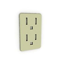
Outlet
...chibase planet
outlet socket wall outlet plug socket
outlet n160914 - 3d model (*.gsm+*.3ds+*.max) for interior 3d visualization.
archibase_planet
free
Outlet
...outlet
archibase planet
socket wall outlet equipment
outlet 03 - 3d model for interior 3d visualization.
3d_ocean
$2
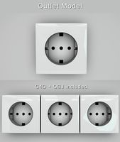
Modern Outlet
...modern outlet
3docean
glossy interior outlet modern outlet outlet white
moder outlet model c4d file and object file included.
archibase_planet
free
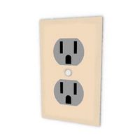
Outlet
...chibase planet
appliance receptacle convenience receptacle receptacle
electrical outlet - 3d model for interior 3d visualization.
turbosquid
$4

Outlet
...t
turbosquid
royalty free 3d model outlet for download as ma on turbosquid: 3d models for games, architecture, videos. (1562268)
3d_export
$5
power outlets
...power outlets
3dexport
power outlets
turbosquid
$15

Outlet
...free 3d model outlet for download as 3ds, obj, fbx, and blend on turbosquid: 3d models for games, architecture, videos. (1194524)
turbosquid
$14

Outlet
...free 3d model outlet for download as 3ds, obj, fbx, and blend on turbosquid: 3d models for games, architecture, videos. (1194499)
turbosquid
$12

Outlet
...free 3d model outlet for download as 3ds, obj, fbx, and blend on turbosquid: 3d models for games, architecture, videos. (1194502)
turbosquid
$10

Outlet
...free 3d model outlet for download as 3ds, obj, fbx, and blend on turbosquid: 3d models for games, architecture, videos. (1194520)
Smart
3ddd
$1

SMART
...smart
3ddd
стул smart
3d_export
$5
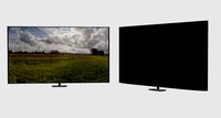
smart tv
...smart tv
3dexport
beautiful smart tv
turbosquid
$15

Smart
... available on turbo squid, the world's leading provider of digital 3d models for visualization, films, television, and games.
3ddd
$1
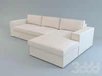
CTSsalotti / Smart
...ctssalotti / smart
3ddd
ctssalotti , угловой
ctssalotti smart 2800х1700
3ddd
$1
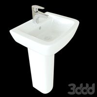
Gala Smart раковина
...gala smart раковина
3ddd
gala , smart
производитель gala
модель smart
design_connected
$13

Smart&Sleek
...smart&sleek
designconnected
wisteria smart&sleek computer generated 3d model.
3d_export
$5

Smart 3D Model
...smart 3d model
3dexport
smart car small mercedes
smart 3d model pio33d 67449 3dexport
3d_export
$15
Smart 3D Model
...smart 3d model
3dexport
smart auto car compact_car compat
smart 3d model savmart 95148 3dexport
3d_export
$12

samsung smart tv
...samsung smart tv
3dexport
samsung smart tv
3ddd
$1
Smart
...smart
3ddd
материалы вирей. модель не моя. переделал под вирей просто.
Switch
archibase_planet
free
Switch
...switch
archibase planet
switch cluster switch
light switch 1 - 3d model for interior 3d visualization.
archibase_planet
free
Switch
...switch
archibase planet
switches switch
switch 1 - 3d model (*.gsm+*.3ds) for interior 3d visualization.
archibase_planet
free
Switch
...switch
archibase planet
closer button switch cluster switch
switch - 3d model (*.3ds) for interior 3d visualization.
archibase_planet
free
Switch
...switch
archibase planet
switch closer
light switch 2 - 3d model for interior 3d visualization.
archibase_planet
free
Switch
...switch
archibase planet
closer button switch
switch n300808 - 3d model (*.gsm+*.3ds) for interior 3d visualization
archibase_planet
free
Switch
...switch
archibase planet
closer button switch
switch n141108 - 3d model (*.gsm+*.3ds) for interior 3d visualization.
archibase_planet
free
Switch
...switch
archibase planet
cluster switch closer
switch n260609 - 3d model (*.gsm+*.3ds) for interior 3d visualization.
archibase_planet
free
Switch
...switch
archibase planet
button switch closer
switch 2 - 3d model (*.gsm+*.3ds) for interior 3d visualization.
archibase_planet
free
Switch
...switch
archibase planet
button switch closer
switch n070510 - 3d model (*.gsm+*.3ds) for interior 3d visualization.
3d_export
$5

switch
...switch
3dexport
3d model of a low-poly switch
Printed
design_connected
$27

...print
designconnected
moroso print computer generated 3d model. designed by wanders, marcel.
3ddd
free

Eichholtz Prints
...- eichholtz print central station i
13 - eichholtz print central station ii
14 - eichholtz print marisa
15 - eichholtz print tish
3ddd
$1

Eichholtz Prints
...print abstract - set of 2
10 - eichholtz print orange abstract
11 - eichholtz print buddha right
12 - eichholtz print buddha left
turbosquid
$1
... available on turbo squid, the world's leading provider of digital 3d models for visualization, films, television, and games.
3ddd
free
Eichholtz Prints
...of 4
2 - print dunbar 2 set of 4
3 - print guadeloupe 1 set of 4
4 - print guadeloupe 2 set of 4
5 - print giles
6 - print trett
3ddd
$1

Eichholtz Prints
...nt tutti frutti
3 - eichholtz prints watson - set of 2
4 - eichholtz prints antique nautilus - set of 2
5 - eichholtz print tiara
3d_export
$5
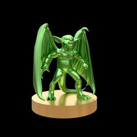
Monster for printing
...monster for printing
3dexport
monster 3d model printing
3ddd
free
printed rug
...printed rug
3ddd
ковер
very creative printed rug
3ddd
free
Eichholtz Prints
...иал: бумага
габариты (вхш): 72 x 62 см
описание: print sweetmeat - постер в деревянной раме.
3 - prints varsity set of 2
арти
3ddd
free
Art Print Posters
...art print posters
3ddd
прованс
art print posters by patrician prints