Thingiverse
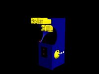
3D Printed 2 Player Arcade Machine by Tetsuo315
by Thingiverse
Last crawled date: 3 years, 3 months ago
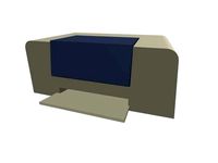
3D Printed Arcade III STEM Project:
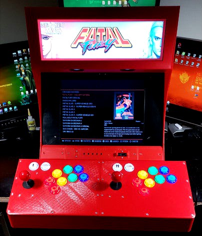
When I began designing my first printed arcade cabinet, it was my goal to design a couple more at different sizes. This one is the largest with a 14 inch display and 2 player controls. Here are some specs on the latest build.
Designed in Fusion 360
Printed on two Creality CR-10 minis
Printed using PLA
Five days of printing spread over two weeks
Active marquee - Updates artwork to match game chosen. The Pixelcade LCD marquee also plays GIF animations for select arcade titles. The product is called Pixelcade LCD. Checkout www.pixelcade.org for information on the solutions they offer.
The marquee is ran by a Raspberry Pi Zero W
Powered by a Raspberry Pi 4 B
All components powered by a buck converter regulator system.
-Here is a viewable only link to the bill of materials for the internal components and mounting hardware I used.
https://docs.google.com/spreadsheets/d/1z_-SHu5X3jC4bZgl-VjIBBc8WmOZwpuI7H0ucnM74FU/edit?usp=sharing
-Here is a link to a video demonstrating some of the features.
https://www.youtube.com/watch?v=W_9i6rsRqQE
-This project started off as something personal. Some individuals became more and more curious and requested access to the STLs. Therefore I am releasing these here as is. I am not an engineer by trade. I am an IT worker with a STEM/STEAM focus for my job. I designed this in the best way I know how. I do not have a lot of time since school has started back up, so revisions will be rare.
-I did my best to factor in enough clearance and tolerance for adjoining parts. In some cases a little sanding may be needed to fit parts together. Linear advance will be to your advantage and to help minimize that "bow tie" effect (that's what I call it at least) on the corners of parts. Also use a deburring tool to clean up edges. That will help parts fit better. This is not perfect by any stretch. Certain things could have been designed better, but I can assure you that once everything is assembled it is pretty sturdy. This is not a cheap build so be prepared to spend over 600 US dollars on this if you use the parts I list. I wanted a specific set of gadgets inside of this, so the machine was designed around said list. Please don't ask me to redesign a part. As I mentioned before this comes as is. As I have time I will post revisions that work with the parts list I provided above.
-Things to keep in mind:
-Disclaimer: If you are not comfortable with soldering or do not have a good understanding of how electronics work together, this project is not for you. If you attempt this build and burn up the buck converters or other components that's on you. I can't and will not claim responsibility for the choices you make or the corners you chose to cut. Take your time. Pretest all of the equipment as a whole before you put it in the cabinet. Create a build plan.
-The brackets used to mount the I/O components on the rear of the cabinet and elserwhere were designed around that particular brand and style. You may need to load this into an STL editing tool and make changes if you can't find that brand of part. Amazon has most if not all of the parts on the list from the above link. I will be very specific with the brand I used or link to that component that's provided in the list.
-The project will require you to solder things. Use a good solder station, quality flux, and helping hands.
-You will need to have access to a multimeter to check continuity on your wiring harness and verify polarity of your power connectors.
-You will need to use a multimeter to set the voltage of the buck converters.
-I used screw terminal male and female barrel jack connectors for all power inputs. These can handle 16-18 gauge wire. Pre-tin your wire ends as much as possible.
-I highly recommend you use the power supply listed in the materials list. It will provide the power system with enough current to drive the components with enough overhead. 24volts with up to 10 amps of current.
-I used JST-SM connectors to create a wiring harness. I purchased a crimping tool to properly terminate the wires that fit into the connector ends. I recommend you use the kit I provide or something close to it. This will keep things nice and prevent unwanted shorts.
-This is a BIG project to undertake. Plan on a couple weeks and few weekends. Have all of the parts purchased a head of time if you can. You will need a little over 3 rolls of 1K filament spools to print this. Have some spare rolls on hand in case you have failed prints. Some of these parts will use over 1/3 of a 1K spool. Some of these files can take over a day to print. On some of those bigger parts you may want to consider a printing service if you can't afford to tie down your printer for over a day. I have provided a lot pictures to give you an idea of how all of this fits together. Please use them.
-Regarding the LCD monitors used for this build:
-The main display used was a JaiHo 14 inch 4:3 cctv monitor. I removed the front part of the bezel and trashed it as it was not needed. You will need to carefully open it with a spudger tool and a sturdy guitar pick that comes in most precision screw driver kits. Don't use a screw driver or anything metal for that matter. Take your time with this. Save the buttons on the bottom for the controls. You will cut these from the clip and repurpose them later.
-The marquee display is specific to the Pixelcade LCD. You can purchase a kit from pixelcade.org or source your own parts and buy just the software. Please use the links in the bill of materials list to get the correct one.
Similar models
thingiverse
free

Wago Holder by Overnau
...s wago holder to the wires.
hope it will help to solve coller connecton problem without soldering.
have a good and stable prints.
thingiverse
free

XT60 2-6S to USB converter by Unboxingexperience7
...ctronics and a plug. simply put the module with the soldered xt60 female connector into the body and then cover it with the plug.
thingiverse
free
Hardwire BEC enclosure for first alert smoke alarm by kelsier
...larm to hard wired.
as a bonus.. put that 12v power source on a ups, then it should still work a while even if the power is out.
thingiverse
free

Dremel Battery Adapter by gabetz89
...pply. i used some 14 gauge solid copper wire to make the contact points and some stranded wire to connect it to the power supply.
grabcad
free

Electric wire connector
...ool that connects two-wires without soldering.
i use pla filament. if use nylon filament it will be better. you need 1 m3 washer.
thingiverse
free
3 Rail Track Power Block by u04601
...e track look nice and neat.
you can see that it is also plugged into the switch that i made and can be found here on thingiverse.
thingiverse
free

Electric wire connector without soldering by zhwang168
...ament. if use nylon filament it will be better. you need 1 m3 washer.
detail information on youtube:https://youtu.be/b-v6h0a3kve
3dwarehouse
free

Bartop Arcade - with modular control panel
...e actual marquee... as it is their's and as such they have a right to their originality. #arcade #bartop #control_panel #mame
thingiverse
free
Wago Holder 2 by Overnau
...from the holder.
hope it will help to solve coller and hotend connecton problem without soldering.
have a good and stable prints.
thingiverse
free

Doodle-Bot by Jmadden99
...want to put some putty, clay, sand or something similar into the counter weight and glue the cap on....
Arcade
3ddd
$1
Simas / Arcade
...dd
simas , simas arcade , тумба
simas arcade 46
3d_export
$5

Arcade
...arcade
3dexport
3ddd
free
Turri / Arcade
...turri / arcade
3ddd
turri , журнальный
turri / arcade
turbosquid
$35

arcade
... available on turbo squid, the world's leading provider of digital 3d models for visualization, films, television, and games.
turbosquid
$15
Arcade
... available on turbo squid, the world's leading provider of digital 3d models for visualization, films, television, and games.
turbosquid
free
Arcade
... available on turbo squid, the world's leading provider of digital 3d models for visualization, films, television, and games.
3d_ocean
$16

Arcade Game
...tomate button coin computer console fun game gamer gaming joystick machine play side art video game
detailed arcade game machine.
3d_export
$5

Arcade 3D Model
...arcade 3d model
3dexport
architecture arcade elements decor
arcade 3d model evgenadm 86783 3dexport
3d_export
$10

Arcade 3D Model
...arcade 3d model
3dexport
arcade arch porch portico well round
arcade 3d model loscarpello 54648 3dexport
3d_export
$9
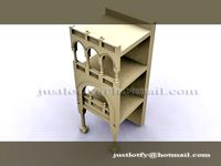
Arcade 3D Model
...arcade 3d model
3dexport
arcade architecture old building classic arch
arcade 3d model lotfy 150 3dexport
Player
archibase_planet
free

Player
...player
archibase planet
player cd player cd
cd player - 3d model for interior 3d visualization.
archibase_planet
free
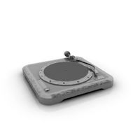
Player
...player
archibase planet
record-player vinyl player
dj vinyl player - 3d model (*.gsm+*.3ds) for interior 3d visualization.
archibase_planet
free
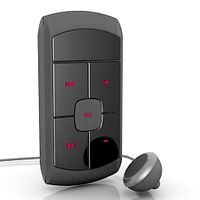
Player
...player
archibase planet
mp3 player equipment player
player mp3 alro n010511 - 3d model (*.3ds) for interior 3d visualization.
archibase_planet
free

Player
...player
archibase planet
mp3 player player equipment
player mp3 n270211 - 3d model (*.gsm+*.3ds) for interior 3d visualization.
archibase_planet
free

Player
...rtable media player
player portable pocket apple ipod nano 4g 8gb n170213 - 3d model (*.gsm+*.3ds) for interior 3d visualization.
archibase_planet
free
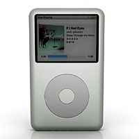
Player
...r
archibase planet
ipod player mp3 player
player ipod classic mp3 n280111 - 3d model (*.gsm+*.3ds) for interior 3d visualization.
archibase_planet
free
Player
...player
archibase planet
equipment player
player - 3d model (*.gsm+*.3ds) for interior 3d visualization.
archibase_planet
free
Player
...player
archibase planet
player equipment
v-player - 3d model (*.gsm+*.3ds) for interior 3d visualization.
archibase_planet
free
Player
...player
archibase planet
dvd player home equipment
player dvd - 3d model (*.gsm+*.3ds) for interior 3d visualization.
archibase_planet
free
Player
...player
archibase planet
player
phono1 - 3d model for interior 3d visualization.
Machine
archibase_planet
free
Machine
...machine
archibase planet
sewing-machine sewing machine equipment
singer machine- 3d model for interior 3d visualization.
archibase_planet
free

Machine
...hine
archibase planet
percolator equipment coffee-machine
machine n230708 - 3d model (*.gsm+*.3ds) for interior 3d visualization.
archibase_planet
free
Machine
...chibase planet
percolator coffee-machine kitchen equipment
coffee machine - 3d model (*.gsm+*.3ds) for interior 3d visualization.
archibase_planet
free
Slot machine
...ase planet
slot machine slot-machine playing machine
slot machine n260311 - 3d model (*.gsm+*.3ds) for interior 3d visualization.
turbosquid
$7

Machine
...ne
turbosquid
royalty free 3d model machine for download as on turbosquid: 3d models for games, architecture, videos. (1391792)
3d_ocean
$10
War machine
...war machine
3docean
camuflage machine robot war war machine
war machine created in 3dmax 2009 15.497-poly count
turbosquid
$7
machine
...turbosquid
royalty free 3d model machine for download as obj on turbosquid: 3d models for games, architecture, videos. (1452674)
3d_ocean
$12
Weighing-machine
...weighing-machine
3docean
market shop weighing-machine
3d model weighing-machine
archibase_planet
free
Sewing machine
...ine
archibase planet
sewing machine sewing-machine
sewing machine n080311 - 3d model (*.gsm+*.3ds) for interior 3d visualization.
archibase_planet
free
Coffee machine
...se planet
coffee machine percolator coffee-machine
coffee machine n010715 - 3d model (*.gsm+*.3ds) for interior 3d visualization.
2
design_connected
$11
No 2
...no 2
designconnected
sibast no 2 computer generated 3d model. designed by sibast, helge.
turbosquid
$6
Cliff Rock 2-2
...uid
royalty free 3d model cliff rock 2-2 for download as obj on turbosquid: 3d models for games, architecture, videos. (1619161)
turbosquid
$29

Book variation 2 2
...3d model book variation 2 2 for download as max, obj, and fbx on turbosquid: 3d models for games, architecture, videos. (1366868)
turbosquid
$22
Classic baluster (2) (2)
...assic baluster (2) (2) for download as max, obj, fbx, and stl on turbosquid: 3d models for games, architecture, videos. (1483789)
turbosquid
$99

Smilodon 2 Pose 2
... available on turbo squid, the world's leading provider of digital 3d models for visualization, films, television, and games.
turbosquid
$20

Barrel Barricade 2-2
... available on turbo squid, the world's leading provider of digital 3d models for visualization, films, television, and games.
turbosquid
$6
Wall Trophy (2) (2)
... available on turbo squid, the world's leading provider of digital 3d models for visualization, films, television, and games.
turbosquid
free
Tire label 2 of 2
... available on turbo squid, the world's leading provider of digital 3d models for visualization, films, television, and games.
3ddd
$1
Кровать, 2 тумбочки, 2 светильника
...кровать, 2 тумбочки, 2 светильника
3ddd
кровать, 2 тумбочки, 2 светильника
нормальное качество
формат 3ds max
без текстур
3ddd
free
Кровать, 2 тумбочки, 2 светильника
...кровать, 2 тумбочки, 2 светильника
3ddd
кровать, 2 тумбочки, 2 светильника
нормальное качество
формат 3ds max
без текстур
Printed
design_connected
$27
...print
designconnected
moroso print computer generated 3d model. designed by wanders, marcel.
3ddd
free

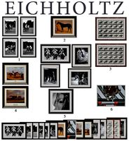
Eichholtz Prints
...- eichholtz print central station i
13 - eichholtz print central station ii
14 - eichholtz print marisa
15 - eichholtz print tish
3ddd
$1

Eichholtz Prints
...print abstract - set of 2
10 - eichholtz print orange abstract
11 - eichholtz print buddha right
12 - eichholtz print buddha left
turbosquid
$1
... available on turbo squid, the world's leading provider of digital 3d models for visualization, films, television, and games.
3ddd
free

Eichholtz Prints
...of 4
2 - print dunbar 2 set of 4
3 - print guadeloupe 1 set of 4
4 - print guadeloupe 2 set of 4
5 - print giles
6 - print trett
3ddd
$1

Eichholtz Prints
...nt tutti frutti
3 - eichholtz prints watson - set of 2
4 - eichholtz prints antique nautilus - set of 2
5 - eichholtz print tiara
3d_export
$5
Monster for printing
...monster for printing
3dexport
monster 3d model printing
3ddd
free
printed rug
...printed rug
3ddd
ковер
very creative printed rug
3ddd
free
Eichholtz Prints
...иал: бумага
габариты (вхш): 72 x 62 см
описание: print sweetmeat - постер в деревянной раме.
3 - prints varsity set of 2
арти
3ddd
free
Art Print Posters
...art print posters
3ddd
прованс
art print posters by patrician prints