Thingiverse
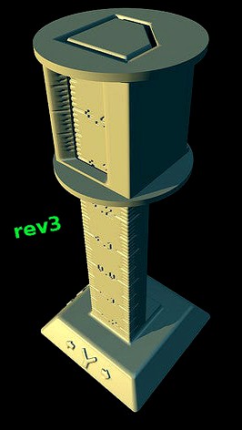
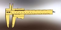
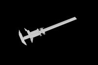
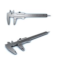
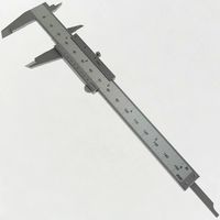
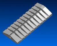
3D Printer Tolerance Vernier revision 3 by Dan_W_58
by Thingiverse
Last crawled date: 3 years ago
Revision 1.5 released July 1st 2018.
For status daily updates, scroll down to the Status section.
This is a tool to assess the dimensional accuracy of printed models.
It can measure tolerance range from negative 0.12 mm to positive 0.37 mm, with micron resolution. (Note that I did NOT say "micron ACCURACY"; --the term "resolution" refers to the finest subdivisions of the reading in a measurement. Absolute accuracy, as well as linearity jitters, are a whole different subject, and they'd depend on cleanliness of the print, on the quality of post-print sanding of blobs and "hairs", on the presence of dust on the tool when measuring, on the presence or absence of build bed shifts during printing causing visible lines, and specially on post-printing dimensional stability and/or warping of the material. PLA is notoriously warp-ish and shrink-ful, for example.)
It is not the printers' fault, usually, that prints turn out half a millimeter bigger, or whereabouts, than they were supposed to be; it is more often the slicer program that makes models slightly bigger in X and Y. The reason for this, I suspect, is that the slicer programmers don't want walls thinner and features smaller than the nozzle diameter to simply disappear altogether; --it would look bad on them even if it's technically correct. Besides, it is much easier for them to check for "collisions" of model surface polygons against a line (the center line of the extrusion), than it is for them to check for collisions against the whole cylindrical extrusion around that center line. I'd do the same in their shoes.
Simplify 3D offers you a parameter you can set to compensate this fattening of the prints; but it is up to you to measure the printing tolerance and put the right number in that compensation box. By default it is zero.
When this value is set, the slicer code reads your stl file and internally shrinks the model by the amount you set (in X and Y; --but not in Z); then computes the gcode. Keep in mind that when you do this, features smaller than your nozzle diameter will simply vanish from the printing!
For most models you probably don't need high accuracy; but if you have mechanical pieces that have to exactly fit into each other, then you definitely need to measure your printing tolerance and adjust the compensation. This Thing allows you to get a finer measurement than most printable tolerance test models can offer, and by a very long shot... down to microns; and it does so using only 2 parts, instead of an entire set.
There are many "Tolerance Test" printable models out there, but all the ones I have seen so far consist of multiple pegs and/or multiple holes, on a large base, to fit the peg(s) into.
I thought, "Wait a minute! A tolerance test tool could be made by having a slightly conical or piramidal long peg and a sliding "hole" piece, which has a mark on it, and you read the tolerance from markings along the peg. No?"
So, I was in the process of implementing just that thought, when it occurred to me that I could get an extra decimal of precision by adding vernier type markings on the sliding piece. Thus, this tool gives you resolution down to MICRONS !!!, if you know how to read a vernier... ;-)
Scroll down to the bottom of this page for a measurement reading example.
Similar models
thingiverse
free
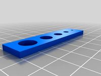
XY Compensation Hole Test by goldengreekpsy
...ers/matterslice/issues/22
the size of the holes are 2mm, 4mm, 6mm, 8mm, 10mm, and the external size of the model is 60mm by 15mm.
3d_export
$50
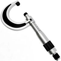
Micrometer 3D Model
...ol industrial measure measurement precision accuracy tolerance dimension mike metric
micrometer 3d model plutonius 33278 3dexport
thingiverse
free

Gap and Line Tester by kohjbeng
...d. this is for your future reference, when you have to design you models so that they can be printable and your designs realised.
thingiverse
free

Vernier type multi-nozzle XY-offsets calibration print (0.05mm precision) by Xiaojun
... ( e.g. 2mm or 3mm per mark) and font (change the typeface variable setting).
any comments or suggestions are appreciated!
thx!
grabcad
free

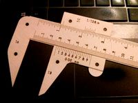
VERNIER CALIPER
...vernier caliper
grabcad
"i used a vernier to measure the vernier"
grabcad
free

Vernier Caliper
...l aid to take an accurate measurement reading between two graduation markings on a linear scale by using mechanical interpolation
thingiverse
free

"Chip Clip" Multi-Tool by badBrick
...3d printer but you're interested in getting one of these we can print you one at badbrick.com/catalog
munch, munch, munch..
thingiverse
free

Bed XY Skew Measurement Strips by fiveangle
...d on thingiverse in order to facilitate ongoing xy calbiration discussion at https://github.com/marlinfirmware/marlin/issues/5116
thingiverse
free

Airsoft PUBG style compensator / muzzle brake by Zvedak
...econd one print as it is with supports everywhere.
if you have problem with thread, set in slicer horizontal expansion to -0,1mm.
thingiverse
free
Laser Cut Paper Calipers with Imperial and Metric Vernier by duckythescientist
...uper thin set of calipers that can be slipped in a binder, folder, or book yet still give accuracy down to a few hundred microns.
Vernier
3d_export
$20
vernier calipper
...vernier calipper
3dexport
vernier cvalipper made as real, exactly scale
3d_export
$7

vernier caliper
... measurement uncertainty by using vernier acuity to reduce human estimation error.<br>please recount polygons and vertices.
turbosquid
$5
Vernier Caliper
...lty free 3d model vernier caliper for download as 3ds and obj on turbosquid: 3d models for games, architecture, videos. (1604280)
3d_ocean
$12
vernier caliper
...9. scene contains 4583 vertex and 4319 faces, textures and materials. the rendering and materials, are set with vray adv 2.10.01.
cg_studio
$30

Vernier Caliper3d model
... model
cgstudio
.3ds .max .obj .wrl - vernier caliper 3d model, royalty free license available, instant download after purchase.
3d_export
$30
Vernier Caliper 3D Model
... metalworking mechanical engineering textures materials photorealistic detailed
vernier caliper 3d model plutonius 33146 3dexport
turbosquid
$1

6" Vernier Calipers
... available on turbo squid, the world's leading provider of digital 3d models for visualization, films, television, and games.
3d_export
$10

digital vernier caliber
...digital vernier caliber
3dexport
texture details:<br>contact me if you need any help. thank you.
3d_export
$50
Micrometer 3D Model
...micrometer 3d model 3dexport micrometer screw gauge dial vernier metrological tool industrial measure measurement precision accuracy tolerance dimension...
3d_export
$5
3D printer filament calibration tool 3D Model
...polycarbonate pc tpe pva measure caliper gauge gage diameter vernier 3d printer filament calibration tool 3d model download .c4d...
Revision
turbosquid
$40

counter display revised
... available on turbo squid, the world's leading provider of digital 3d models for visualization, films, television, and games.
turbosquid
$30

Cascade sewage revision shaft crosscut
... available on turbo squid, the world's leading provider of digital 3d models for visualization, films, television, and games.
3d_export
$10

room interior design model 001
...not be afraid, you can ask me for the revision by contact me with email, i will do it...
3d_export
$15
engineering drone scifi
...loads, fly, shoot, drill, mine.<br>fully rigged. animated fly (need revision. modelled and rigged in blender. textured in substance painter.<br>textures:...
cg_studio
$30

Apple iphone 4 Cell Phone LAST revision3d model
...4d .wrl .wrz - apple iphone 4 cell phone last revision 3d model, royalty free license available, instant download after purchase.
3d_export
$7

ficus alii plant
...2016.09.06 16:32<br>formfactor: circle<br>style: modern<br>material: metal organics<br>color:<br>description<br>ficus plants ,,, small revision in modeling ,,, max2015,2012 & fbx ,,...
3d_export
$10

antonio lupi design timbro
...ollection. timbro is available top or wall mount and freestanding also. timbro tops are made of polished<br>chrome brass.
3d_export
free
bed - sample
...game and animation.<br>- custom texture with 4k resolution png format.<br>revision (24/12/2020)<br>- reupload with new fbx format.<br>- edge loops added...
3d_export
$60

mitsubishi galant 1996 - 1999 -- 8th generation -- sedan
...ented as separate objects. if you have any difficulties or need a model in a certain format, write and we will solve the problem.
3d_export
$27

the latest automatic n95 mask machine production line drawings
...trasonic heat sealing system. the whole machine has stable performance, high production efficiency and high degree of automation.
58
turbosquid
$1

58
...58
turbosquid
royalty free 3d model 58 for download as stl on turbosquid: 3d models for games, architecture, videos. (1158783)
3ddd
$1

Pillows 58
...pillows 58
3ddd
подушка
pillows 58. i hope you like it.thank you
turbosquid
$20

Bath 58
... free 3d model bath 58 for download as max, dxf, fbx, and dwg on turbosquid: 3d models for games, architecture, videos. (1277090)
turbosquid
$29

house 58
... available on turbo squid, the world's leading provider of digital 3d models for visualization, films, television, and games.
turbosquid
$25

Ring 58
... available on turbo squid, the world's leading provider of digital 3d models for visualization, films, television, and games.
turbosquid
$9

Office 58
... available on turbo squid, the world's leading provider of digital 3d models for visualization, films, television, and games.
turbosquid
$4

Basin 58
...3d model basin 58 for download as 3ds, max, dxf, fbx, and dwg on turbosquid: 3d models for games, architecture, videos. (1285461)
turbosquid
$3

chair - 58
... available on turbo squid, the world's leading provider of digital 3d models for visualization, films, television, and games.
turbosquid
$7

Vase 58
...odel vase 58 for download as max, max, 3ds, fbx, obj, and stl on turbosquid: 3d models for games, architecture, videos. (1539603)
3ddd
$1

Кухня 58
...кухня 58
3ddd
кухня, барная стойка - триарт
Tolerance
turbosquid
$3
Low polygonal tolerant bear
... polygonal bear for download as 3ds, obj, fbx, blend, and stl on turbosquid: 3d models for games, architecture, videos. (1392956)
3d_export
$50
Micrometer 3D Model
...dial vernier metrological tool industrial measure measurement precision accuracy tolerance dimension mike metric micrometer 3d model plutonius 33278...
3d_export
$12
clutch assembly line
...clutch assembly line 3dexport according to the principle of tolerance fit from left to right in the general assembly...
3d_export
$5
puzzle cube
...functions of your printer. i have left some extra tolerance at the bridge location to account for some sagging....
3d_export
$9

beskar mandalorian steel
...alloy used in mandalorian armor, notable for its high tolerance to extreme forms of damage. the metal was durable...
3d_export
$5

4 spring Azalea Flower Bush
...50cm bush 2 : 160cm bush 3 : 170cm bush 4 : 180cm formats 3ds max - vray / corona cinema 4d - vray / standard blender obj fbx stl
3d_export
$10
varonoi lamp
...cm. al of the components are designed with small tolerance which can make it hard to scale down, but...
3d_export
$20
9KH30 Ring die pellet machine
...be smoothly made for sale according to the dimensions, tolerance and technical requirements. the characteristics of the pellet machine...
3d_export
$5

Douglas Fir Forest trees
...ats<br>3ds max - vray / corona<br>cinema 4d - vray / standard<br>blender<br>obj<br>fbx<br>stl
3d_export
$20
mech-spider-ninjia
...22815 verts:23663<br>animation clips: idle walk jump attack<br>textures format: jpg.<br>texture size: 4096*4096
Dan
3ddd
free
Dan Mansion
...dan mansion
3ddd
dan mansion , барный
dan mansion
turbosquid
$13

Dan dan dandelion
...del leafless dandelion for download as lwo, fbx, dae, and obj on turbosquid: 3d models for games, architecture, videos. (1691938)
3ddd
$1
Itomaki by Dan Sunaga
...omaki by dan sunaga
3ddd
dan sunaga , журнальный
itomaki coffetable design by dan sunaga
3ddd
$1
DOLPHIN DAN-FORM
...dolphin dan-form
3ddd
dolphin , dan-form
стул из каталога dan-form
3ddd
free
DAN-FORM ZEUS
...dan-form zeus
3ddd
dan-form , zeus
красивый стул dan-form zeus
3ddd
free
DAN-FORM APOLLO
...dan-form apollo
3ddd
dolphin , dan-form
классический стул из каталога dan-form.
turbosquid
free

Crocodile dan
...n
turbosquid
free 3d model crocodile dan for download as max on turbosquid: 3d models for games, architecture, videos. (1154058)
3ddd
$1
Agnes DAN-FORM
...agnes dan-form
3ddd
agnes
модель стула agnes из каталога dan-form
turbosquid
$14

Counterbalance by Dan Yeffet
...ounterbalance by dan yeffet for download as max, obj, and fbx on turbosquid: 3d models for games, architecture, videos. (1453558)
turbosquid
$22

dan wesson revolver
... available on turbo squid, the world's leading provider of digital 3d models for visualization, films, television, and games.
W
3ddd
$1
chair W
...chair w
3ddd
chair w
3ddd
$1

кресло w
...кресло w
3ddd
капитоне
кресло w
3ddd
$1
KUTEK (W) W-ZW-5
...kutek (w) w-zw-5
3ddd
kutek
3d модель люстри (w) w-zw-5 фабрики kutek. в архиве: max2012, obj, fbx, mat.(два варианта металла)
3ddd
$1
KUTEK (W) W-ZW-3
...kutek (w) w-zw-3
3ddd
kutek
3d модель люстри (w) w-zw-3 фабрики kutek. в архиве: max2012, obj, fbx, mat. (два варианта металла)
3ddd
$1
KUTEK (W) W-ZW-1
...kutek (w) w-zw-1
3ddd
kutek
3d модель люстри (w) w-zw-1 фабрики kutek. в архиве: max2012, obj, fbx, mat (два варианта металла).
3ddd
free
aneken W&W
...aneken w&w
3ddd
2 женских манекена, ценники и фолио. материалы и текстуры прилагаются.
design_connected
$9
KTribe W
...ktribe w
designconnected
ktribe w computer generated 3d model. designed by starck, philippe.
design_connected
$16

Troy W
...troy w
designconnected
magis troy w computer generated 3d model. designed by wanders, marcel.
turbosquid
$9
Menu - Benjamin Hubert - W W Carafe
... available on turbo squid, the world's leading provider of digital 3d models for visualization, films, television, and games.
turbosquid
$9
Menu - Benjamin Hubert - W W Carafe
... available on turbo squid, the world's leading provider of digital 3d models for visualization, films, television, and games.
Printer
archibase_planet
free
Printer
...inter
archibase planet
printer laser printer pc equipment
printer n120614 - 3d model (*.gsm+*.3ds) for interior 3d visualization.
archibase_planet
free
Printer
...rchibase planet
laser printer office equipment computer equipment
printer - 3d model (*.gsm+*.3ds) for interior 3d visualization.
turbosquid
$100
Printer
...er
turbosquid
royalty free 3d model printer for download as on turbosquid: 3d models for games, architecture, videos. (1487819)
turbosquid
$1
printer
...turbosquid
royalty free 3d model printer for download as max on turbosquid: 3d models for games, architecture, videos. (1595546)
turbosquid
$1
printer
...turbosquid
royalty free 3d model printer for download as max on turbosquid: 3d models for games, architecture, videos. (1595105)
turbosquid
$7
Printer
...royalty free 3d model printer for download as ma, ma, and obj on turbosquid: 3d models for games, architecture, videos. (1644580)
turbosquid
$30

Printer
... available on turbo squid, the world's leading provider of digital 3d models for visualization, films, television, and games.
turbosquid
$20

Printer
... available on turbo squid, the world's leading provider of digital 3d models for visualization, films, television, and games.
turbosquid
$18
printer
... available on turbo squid, the world's leading provider of digital 3d models for visualization, films, television, and games.
turbosquid
$6

printer
... 3d model printer for download as 3ds, max, dxf, obj, and fbx on turbosquid: 3d models for games, architecture, videos. (1276861)
3
turbosquid
$10
Mountain Bike 3 -3 of 3
...model mountain bike 3 (#3 of 3) for download as fbx and blend on turbosquid: 3d models for games, architecture, videos. (1438752)
turbosquid
$3

Genesis 3 Clothing 3
... available on turbo squid, the world's leading provider of digital 3d models for visualization, films, television, and games.
3d_export
$5
hinge 3
...hinge 3
3dexport
hinge 3
3ddd
$1
Розетка 3
...розетка 3
3ddd
розетка
розетка 3
turbosquid
$50
is-3
... available on turbo squid, the world's leading provider of digital 3d models for visualization, films, television, and games.
turbosquid
$10
Mountain Bike 3 -2 of 3
...model mountain bike 3 (#2 of 3) for download as fbx and blend on turbosquid: 3d models for games, architecture, videos. (1438750)
turbosquid
$10
Mountain Bike 1 -3 of 3
...model mountain bike 1 (#3 of 3) for download as fbx and blend on turbosquid: 3d models for games, architecture, videos. (1438743)
3d_export
$5

3 CATS
...3 cats
3dexport
3 cats pen holder
3ddd
free
3 Буфета
...3 буфета
3ddd
буфет , кантри
3 буфета
turbosquid
$12

Calligraphic Digit 3 Number 3
...hic digit 3 number 3 for download as max, obj, fbx, and blend on turbosquid: 3d models for games, architecture, videos. (1389329)