Thingiverse
3 Channel PWM Controller by ScribbleJ
by Thingiverse
Last crawled date: 4 years, 7 months ago
This is a basic design for a 3-channel PWM controller, like you might use to control a string of 12v RGB LEDs, like these, maybe:
http://www.dealextreme.com/p/rgb-multicolored-1-meter-30-led-6w-light-strip-dc-12v-14965 (fun, because you can just cut it to the length you want, in minimum units of ~3 inches)
I've got a few different things I want to do with this, but it was mainly a way for me to try designing and etching my first PCB.
FEATURES:
Custom Arudino bootloader (kinda)
Three 200ma(ea) 12v PWM channels
Three analog input pins
Runs on 12v (good for use in a car!)
Minimal part count
Simple
WIP WHY:
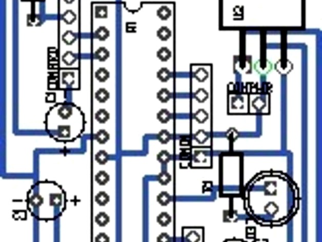
All the photos are of the first design, which as you can see, had a lot of mistakes requiring jumpering and trace-cutting. I think they have all been solved in the uploaded schematic, but I haven't had an opportunity to print a new one to test.
The first design schematics are lost, sorry. :(
I'm using a custom arduino bootloader (will be provided below) and included an arduino pinout but I cannot get the arduino programmer to communicate with my Atmega8. It does serial comms over those lines fine, otherwise. Help appreciated.
I've /just/ used this in my first design (to be published shortly) so I'm still testing it. Seems to work well these last few hours at least!
The transistor breakout board (the tc* files) I had to build on a protoboard as we've got a cold snap and I'm a wimp who will not go outside to etch if the weather is less than perfect. As soon as it warms up a bit I'll be printing that and the new mainboard. I might combine them.
http://www.dealextreme.com/p/rgb-multicolored-1-meter-30-led-6w-light-strip-dc-12v-14965 (fun, because you can just cut it to the length you want, in minimum units of ~3 inches)
I've got a few different things I want to do with this, but it was mainly a way for me to try designing and etching my first PCB.
FEATURES:
Custom Arudino bootloader (kinda)
Three 200ma(ea) 12v PWM channels
Three analog input pins
Runs on 12v (good for use in a car!)
Minimal part count
Simple
WIP WHY:
All the photos are of the first design, which as you can see, had a lot of mistakes requiring jumpering and trace-cutting. I think they have all been solved in the uploaded schematic, but I haven't had an opportunity to print a new one to test.
The first design schematics are lost, sorry. :(
I'm using a custom arduino bootloader (will be provided below) and included an arduino pinout but I cannot get the arduino programmer to communicate with my Atmega8. It does serial comms over those lines fine, otherwise. Help appreciated.
I've /just/ used this in my first design (to be published shortly) so I'm still testing it. Seems to work well these last few hours at least!
The transistor breakout board (the tc* files) I had to build on a protoboard as we've got a cold snap and I'm a wimp who will not go outside to etch if the weather is less than perfect. As soon as it warms up a bit I'll be printing that and the new mainboard. I might combine them.