Thingiverse
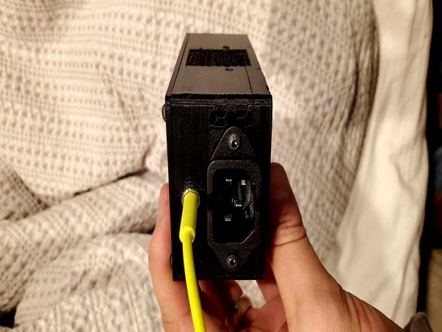
12v Trigger Relay Outlet
by Thingiverse
Last crawled date: 4 years, 2 months ago
Obligatory warning: Wiring involves main electricity. Do not wire while live. Do not attempt build unless you know what you are doing.
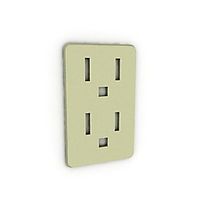
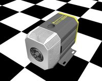
I use a vintage amp that does not have a 12v trigger line. It also lacks a remote and I'm lazy. This uses a 12v trigger relay from my receiver to switch power. Power in through an IEC cable and out through a 3 prong outlet.
BOM:
12v relay: https://www.mouser.com/ProductDetail/655-T9AP1D52-12
Panel mount IEC: https://www.parts-express.com/parts-express-iec-ac-power-jack-chassis-mount--090-442
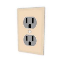
Panel mount 3 prong: https://www.mouser.com/ProductDetail/562-738W-X2-01
Heatsink: https://www.mouser.com/ProductDetail/567-642-35AB
3.5mm panel mount jack (mono or stereo)
8 x 3mm screws
2 x 3mm nuts
14-16 & 18 awg wire
4 female .25 terminals
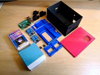
Build:
Put all the pieces together without screws. This will help ensure the wiring goes where it is needed. I'm not sure if the relay needs a heat sink but I had one laying around. I attached it to the back of the relay using thermal tape. It should be flush on the bottom. Be sure to orient the fins horizontally so that air can flow from end to end of the box.
Solder wire ground and Neutral from both outlets together using the larger wire
Create two wires with female terminals using the larger wire to connect the outlet hot pins to the relay switched output
Wire the tip of the 3.5mm to one end of the trigger pin on the relay using a female connector. Wire the ground (and barrel together, if using stereo) to the other trigger pin relay
Test 12v trigger using 3.5mm cable from source. Check continuity on the hot line and make sure that none of your wires are crosses/shorted.
Put the lid on before testing with mains connected
Plug in power to the box but DO NOT CONNECT A DEVICE. Test power at the output.
Enjoy your switched outlet
I use a vintage amp that does not have a 12v trigger line. It also lacks a remote and I'm lazy. This uses a 12v trigger relay from my receiver to switch power. Power in through an IEC cable and out through a 3 prong outlet.
BOM:
12v relay: https://www.mouser.com/ProductDetail/655-T9AP1D52-12
Panel mount IEC: https://www.parts-express.com/parts-express-iec-ac-power-jack-chassis-mount--090-442
Panel mount 3 prong: https://www.mouser.com/ProductDetail/562-738W-X2-01
Heatsink: https://www.mouser.com/ProductDetail/567-642-35AB
3.5mm panel mount jack (mono or stereo)
8 x 3mm screws
2 x 3mm nuts
14-16 & 18 awg wire
4 female .25 terminals
Build:
Put all the pieces together without screws. This will help ensure the wiring goes where it is needed. I'm not sure if the relay needs a heat sink but I had one laying around. I attached it to the back of the relay using thermal tape. It should be flush on the bottom. Be sure to orient the fins horizontally so that air can flow from end to end of the box.
Solder wire ground and Neutral from both outlets together using the larger wire
Create two wires with female terminals using the larger wire to connect the outlet hot pins to the relay switched output
Wire the tip of the 3.5mm to one end of the trigger pin on the relay using a female connector. Wire the ground (and barrel together, if using stereo) to the other trigger pin relay
Test 12v trigger using 3.5mm cable from source. Check continuity on the hot line and make sure that none of your wires are crosses/shorted.
Put the lid on before testing with mains connected
Plug in power to the box but DO NOT CONNECT A DEVICE. Test power at the output.
Enjoy your switched outlet
Similar models
grabcad
free

STEREO AUDIO CONNECTOR (FEMALE) 3.5MM
...nector (female) 3.5mm
grabcad
connector audio (female) stereo threaded with nut panel mount 3.5mm 4 pins.
cui part #sj5-43502pm
3dwarehouse
free

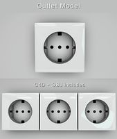
IEC 60320 C13 female panel snap-in AC mains power outlet
...iec 60320 c13 female panel snap-in ac mains power outlet
3dwarehouse
iec 60320 c13 female panel snap-in ac mains power outlet
3dwarehouse
free

3-way IEC 60320 C13 female panel snap-in AC mains power outlet
... 60320 c13 female panel snap-in ac mains power outlet
3dwarehouse
3-way iec 60320 c13 female panel snap-in ac mains power outlet
3dwarehouse
free

2-way IEC 60320 C13 female panel snap-in AC mains power outlet
... 60320 c13 female panel snap-in ac mains power outlet
3dwarehouse
2-way iec 60320 c13 female panel snap-in ac mains power outlet
thingiverse
free

Switch mount for MendelMax by LulzBot
...you can find the switch we use on mouser here: ca.mouser.com/productdetail/e-switch/re111c1121/?qs=s%2fcbhqs5rcobvmsgnwxbha%3d%3d
thingiverse
free

inline housing for a 4 pin Jones plug or socket 38330-0104 by davepix
...2bcq%3d%3dhttp://www.mouser.com/productdetail/molex/38331-5604/?qs=%2fha2pyfaduihkuy2pbp6qas6wupl2htnzggentf0ekibeczqjmmvsq%3d%3d
thingiverse
free
OctoPrint Dual instances control box by Sp4wN
...fit in the box, or you can buy a similar one:https://www.aliexpress.com/item/ugreen-usb-2-0-type-a-male-to-b-male-printer-cable-sync-data-charger-cable/32416310263.html dupont wires:https://www.aliexpress.com/item/wavgat-dupont-line-120pcs-20cm-male-to-male-male-to-female-and-female-to-female-jumper/32501238474.html usb hub i have used is...
thingiverse
free

Switched relay box by tkbletsc
...9;s live, and it can start a fire if wired wrong or with insufficient gauge wire (18awg to probably not die, 14awg to meet code).
thingiverse
free

M28 Panel Mount Powerpole
...required, but you may want to adapt it for similar use. this is a remix of my m28 panel...
grabcad
free

Power Connector IEC C14 3 pins
...power connector iec c14 3 pins
grabcad
male connector iec c14 3 pins for panel mount
Relay
turbosquid
$50
Relay Spaceship
... model relay spaceship for download as skp, 3ds, dae, and obj on turbosquid: 3d models for games, architecture, videos. (1655800)
3ddd
$1

Scavolini / Grand Relais
...scavolini / grand relais
3ddd
scavolini
scavolini модель grand relais дизайн gianni pareschi
3ddd
$1
Сантехника Globo Relais
... унитаз , зеркало
сантехника globo relais
умывальник,зеркало,унитаз.
3d_export
$8
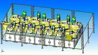
relay automatic assembly line
...relay automatic assembly line
3dexport
relay automatic assembly line
3ddd
free

Унитаз и биде Relais
... биде , унитаз
унитаз art.re001 bi и биде art.re009 bi
turbosquid
free

Relay 8 pin
... available on turbo squid, the world's leading provider of digital 3d models for visualization, films, television, and games.
cg_studio
$110

Power relay station3d model
...el
cgstudio
.3ds .fbx .max .obj - power relay station 3d model, royalty free license available, instant download after purchase.
3ddd
$1
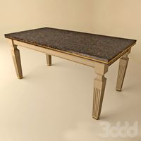
Стол обеденный -Scavolini- Grand Relais
...s
3ddd
обеденный , scavolini
обеденный стол scavolini - grand relais, в трёх расцветках.
3d_export
$10
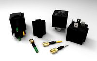
relay jd1912 12v 40a with connector
...lowing bodies: 1. relay jd1912 12v 40a - 1 piece; 2. connector housing - 1 piece; 3. terminal with a part of the wire - 4 pieces.
3ddd
free

Globo Relais furnitures
... , раковина
раковина с консолью st070.ne
зеркалоsp070.bi
стакан re0381x
мыльница re0391x
Trigger
turbosquid
free

Detonation Trigger
... available on turbo squid, the world's leading provider of digital 3d models for visualization, films, television, and games.
turbosquid
$15

Clown Trigger Fish
...
royalty free 3d model clown trigger fish for download as max on turbosquid: 3d models for games, architecture, videos. (1237215)
3d_ocean
$10

Arrow Shooting Trap with Triggers
...3d model. ready for game. good for mobile games. good for rts games. 826 tris and 454 verts textures are 1024×1024. png, tga, psd
turbosquid
$7

Bottle Trigger Sprayer 3
...prayer 3 for download as blend, blend, 3ds, dae, fbx, and obj on turbosquid: 3d models for games, architecture, videos. (1546940)
turbosquid
$7

Bottle Trigger Sprayer 2
...prayer 2 for download as blend, blend, 3ds, dae, fbx, and obj on turbosquid: 3d models for games, architecture, videos. (1546929)
turbosquid
$7

Bottle Trigger Sprayer 1
...prayer 1 for download as blend, blend, 3ds, dae, fbx, and obj on turbosquid: 3d models for games, architecture, videos. (1546911)
turbosquid
$7

Bottle Trigger Sprayer 4
...prayer 4 for download as blend, blend, 3ds, dae, fbx, and obj on turbosquid: 3d models for games, architecture, videos. (1546952)
3d_export
$10

Trigger Snap Hook 3D Model
...ty climbing snap-hook snap-link link shackle holder latch swivel ring equipment
trigger snap hook 3d model firdz3d 88191 3dexport
3d_export
$5

undulate trigger fish low poly
...undulate trigger fish low poly
3dexport
3d_export
$5

reef trigger fish low poly
...reef trigger fish low poly
3dexport
Outlet
archibase_planet
free
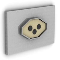
Outlet
...chibase planet
outlet socket wall outlet plug socket
outlet n160914 - 3d model (*.gsm+*.3ds+*.max) for interior 3d visualization.
archibase_planet
free
Outlet
...outlet
archibase planet
socket wall outlet equipment
outlet 03 - 3d model for interior 3d visualization.
3d_ocean
$2
Modern Outlet
...modern outlet
3docean
glossy interior outlet modern outlet outlet white
moder outlet model c4d file and object file included.
archibase_planet
free
Outlet
...chibase planet
appliance receptacle convenience receptacle receptacle
electrical outlet - 3d model for interior 3d visualization.
turbosquid
$4

Outlet
...t
turbosquid
royalty free 3d model outlet for download as ma on turbosquid: 3d models for games, architecture, videos. (1562268)
3d_export
$5
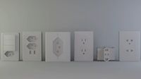
power outlets
...power outlets
3dexport
power outlets
turbosquid
$15

Outlet
...free 3d model outlet for download as 3ds, obj, fbx, and blend on turbosquid: 3d models for games, architecture, videos. (1194524)
turbosquid
$14

Outlet
...free 3d model outlet for download as 3ds, obj, fbx, and blend on turbosquid: 3d models for games, architecture, videos. (1194499)
turbosquid
$12

Outlet
...free 3d model outlet for download as 3ds, obj, fbx, and blend on turbosquid: 3d models for games, architecture, videos. (1194502)
turbosquid
$10

Outlet
...free 3d model outlet for download as 3ds, obj, fbx, and blend on turbosquid: 3d models for games, architecture, videos. (1194520)
12V
turbosquid
$6

12v battery
...royalty free 3d model 12v battery for download as max and fbx on turbosquid: 3d models for games, architecture, videos. (1355531)
3ddd
$1

Dolce Porte / Venezia 12V
...
3ddd
dolce porte , дверь
багетные межкомнатные двери dolce porte , полотно 2000х800 mm.
3d_export
$15
Aquacomputer Aquastream XT USB 12V Pump 3D Model
...
water cooling pomp aquacomputer aquastream xt computer
aquacomputer aquastream xt usb 12v pump 3d model mackandco 37582 3dexport
3d_export
$10
relay jd1912 12v 40a with connector
...lowing bodies: 1. relay jd1912 12v 40a - 1 piece; 2. connector housing - 1 piece; 3. terminal with a part of the wire - 4 pieces.
3d_export
$5

CHC3512CB fan
...chc3512cb fan 3dexport solidworks 3d model of chc3512cb 35mm 12v fan for...
3ddd
free

Люстра Quasar
...sizes: *38 x e 5/8 12v/1.2w 1 x gy6.35 12v75w l 76 x e 5/8 6v/1.2w 1 x gy6.35...
3ddd
$1

MW-LIGHT Федерика
...379013512 высота 34 см диаметр 55 см 12х20w g4 12v рекомендуемая площадь освещения: 16 кв....
3ddd
$1

ILFARI. TEARS FROM MOON H34
...munsters описание: 34 x g4 | 10w max. | 12v включительно светильники 4 x led 3.2w | 2700k |...
3ddd
$1

ILFARI. TEARS FROM MOON H22
...munsters описание: 22 x g4 | 10w max. | 12v включительно светильники 3 x led 3.2w | 2700k |...
3ddd
$1

Lightstar / Boogie Vetro OP
...источники света: 1x50wmax gu5,3 (mr16) (лампой не комплектуется) напряжение: 12v220v диаметр: 80мм высота: 70мм диаметр врезного отверстия: 55мм глубина...