Thingiverse
Gyroscopic Lamp by doby
by Thingiverse
Last crawled date: 2 years, 11 months ago
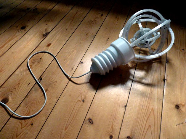
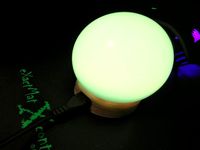
Designed solely for the S.T.E.A.M technology challenge, Light It Up, this lamp was inspired by wondering if I could create something that would replicate swarming fireflies. Essentially its a lamp with gyroscopic moving parts intended for use inside and out (although its not waterproof so cannot be left outside).
The overall design of the lamp is based on a classic spherical screw cap bulb. I tried to make it look as good when operational as it does when not in use and seeing how night and day are fairly even in duration it was an important factor to consider during the design stage.
How it works:
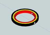
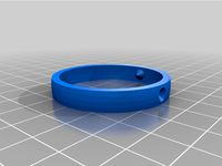
The lamp has 4 rings and a central orb connected with axles and bearings through which current flows. For every ring, every opposing axel is a positive and negative input, and so eventually electricity gets to the orb in the middle by linking the rings up (or so I thought, more on that later...)
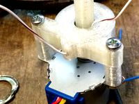
Each ring has 12 yellow flicker LEDs and the orb in the center has 48 yellow flicker LEDs. The outer ring is connected to a motor hidden in the screw cap of the bulb shape to spin the rings. There's also a motor inside the orb connected to a weight which displaces the weight in the orb to counter balance the rings alignment when spinning horizontally. The result being that the rings should be in a constant state of movement around their axes in different directions. Also hidden in the screw cap is all the circuitry for the lamp.
The lamp is triggered by an IR sensor located in the nipple of the bulb shape. There are 2 voltage ramp circuits to power the main motor and LEDs/orb motor. When triggered the outer ring will slowly build up speed and the LED's will fade on then, once the IR circuit cuts the power after an allotted time, the outer ring will slowly decrease its speed and the LED's will fade off.
The screw cap and the dome contact point of the bulb shape have both been designed with twist and lock mechanisms to enable easy access to the circuitry once the model has been fully built. This gives easy access if you need to troubleshoot something or alter the ramp times of the ramp circuits and trigger duration for the IR circuit.
Confessions:
Admittedly the design needs more work, currently the electrical current is having difficulty reaching the centre due to the poor connections provided by the bearings and as a result there is a steep voltage drop off. However I'm out of time for the challenge so I'm submitting it as it is. I think I've made pretty good progress for a fairly ambitious and unpredictable project and as it stands at the moment its still pretty cool.
Future revisions:
I intend to address these issue in the coming weeks, using a slip ring to guarantee a stable connection into the largest ring and then refining the bearing and axel connections. I could also replace the resistors in the rings using larger values for the outermost larger rings and reducing the values as they go inwards reflecting the voltage drop from the bearing connections. This would allow me to run the LEDs safely at a higher voltage whilst still reaching the target voltage of 4.5V for the orb.
Powered by 12V (3A roughly), with an inbuilt DC regulator powering the LED's/orb motor at 4.5V.
Designed in Rhino. All meshes are manifold (watertight).
Videos:
Operational: http://youtu.be/thDSA45_KGY
What it should look like fully illuminated (minus the rotation): http://youtu.be/S3ub-kNEwfA
The overall design of the lamp is based on a classic spherical screw cap bulb. I tried to make it look as good when operational as it does when not in use and seeing how night and day are fairly even in duration it was an important factor to consider during the design stage.
How it works:
The lamp has 4 rings and a central orb connected with axles and bearings through which current flows. For every ring, every opposing axel is a positive and negative input, and so eventually electricity gets to the orb in the middle by linking the rings up (or so I thought, more on that later...)
Each ring has 12 yellow flicker LEDs and the orb in the center has 48 yellow flicker LEDs. The outer ring is connected to a motor hidden in the screw cap of the bulb shape to spin the rings. There's also a motor inside the orb connected to a weight which displaces the weight in the orb to counter balance the rings alignment when spinning horizontally. The result being that the rings should be in a constant state of movement around their axes in different directions. Also hidden in the screw cap is all the circuitry for the lamp.
The lamp is triggered by an IR sensor located in the nipple of the bulb shape. There are 2 voltage ramp circuits to power the main motor and LEDs/orb motor. When triggered the outer ring will slowly build up speed and the LED's will fade on then, once the IR circuit cuts the power after an allotted time, the outer ring will slowly decrease its speed and the LED's will fade off.
The screw cap and the dome contact point of the bulb shape have both been designed with twist and lock mechanisms to enable easy access to the circuitry once the model has been fully built. This gives easy access if you need to troubleshoot something or alter the ramp times of the ramp circuits and trigger duration for the IR circuit.
Confessions:
Admittedly the design needs more work, currently the electrical current is having difficulty reaching the centre due to the poor connections provided by the bearings and as a result there is a steep voltage drop off. However I'm out of time for the challenge so I'm submitting it as it is. I think I've made pretty good progress for a fairly ambitious and unpredictable project and as it stands at the moment its still pretty cool.
Future revisions:
I intend to address these issue in the coming weeks, using a slip ring to guarantee a stable connection into the largest ring and then refining the bearing and axel connections. I could also replace the resistors in the rings using larger values for the outermost larger rings and reducing the values as they go inwards reflecting the voltage drop from the bearing connections. This would allow me to run the LEDs safely at a higher voltage whilst still reaching the target voltage of 4.5V for the orb.
Powered by 12V (3A roughly), with an inbuilt DC regulator powering the LED's/orb motor at 4.5V.
Designed in Rhino. All meshes are manifold (watertight).
Videos:
Operational: http://youtu.be/thDSA45_KGY
What it should look like fully illuminated (minus the rotation): http://youtu.be/S3ub-kNEwfA
Similar models
3dwarehouse
free

low-poly LED light bulb
...ght #light_up #lightning #like #low #material #motor #orbs #plastic #poly #polygon #powered #sphere #tiny_wire #transmit #voltage
thingiverse
free
Cap for 5.5MM DC jack (DC power connector, Type-C Trigger Cable) by toonaoki
...rom short-circuiting.
it has a marker to identify the voltage of the trigger cable.
i recommend printing with flexible filaments.
thingiverse
free

Bulb base for lamp by Lorddrake
...bulb base for lamp by lorddrake
thingiverse
this is a base i designed to hold a led flicker bulb in a lantern
thingiverse
free

Lamp Holder by Lorddrake
...lamp holder by lorddrake
thingiverse
this is a hand to hold a led flicker bulb lamp that i made for a cosplay
thingiverse
free

Piston/Connecting rod shaped LED flashlight
...tton batteries (4.5v in total).
i shared the assembly way ( refer to the gif) and the simply circuit used for the led flaslight.
3dwarehouse
free

Simple Wind Turbine
...e regulator to control battery power... #bearing #electric_motor #electricity #led #renewable_energy #turbine #wind #wind_turbine
thingiverse
free
Slip Ring with 608 Bearing for 28BYJ-48 Stepper Motor by pantonvich
...d the common via the motor shaft.
i've only passed power i.e. 5 volts to light some leds in a moving doll head for halloween.
thingiverse
free
45mm C-ring with 28mm inner radius and outer recess for a Edison Screw bulb mount by ikromin
...w bulb mount by ikromin
thingiverse
just a c-ring i needed to replace for a lamp that uses an edison screw light bulb connector.
thingiverse
free
Universal RGB WiFi indicator BULB
...ws2812 5050 rgb ring-led an esp8266-board (wemos d1 or similar soldered one i/o pin and power +5v/gnd programmed based...
cg_trader
$2

LED Bulb light
...fluorescent power light energy socket saving bulb electric led voltage electrical electricity interior other led light light bulb
Doby
3d_ocean
$8

Human Comics Male - Low Poly Base Mesh
...mesh body character comics comics male fbx human human doby human male human mesh low poly low poly mesh...
sketchfab
$15

Dobi
...(png) * glass
extra optimized are other materials..... - dobi - buy royalty free 3d model by francesco coldesina (@topfrank2013)
cg_trader
$9

Aromas del Campo Dobi Table Lamp
...n pendant bronze gold brass luster wall lamp wall light torchere table lamp spotlight architectural pendant lamp lighting pendant
cg_trader
$10

Dobi Pendant Light From Seed Design
...dobi pendant light from seed design
cg trader
ceiling lights by: seed design
grabcad
free

Doby-1
...doby-1
grabcad
dogs need helmets too!
3dwarehouse
free

nám. Krále Jiřího z Poděbrad 496, Cheb, 350 02 - Špalíček
...půdorys těchto 2 bloků v podstatě zachován do dnešní doby zbořena byla třetí řada domů, která stála na západní...
3dwarehouse
free

Hinchliffe Stadium
...brightest stars, including the legendary hall of famer larry doby who tried out for the newark eagles at hinchliffe...
3dwarehouse
free

Stará radnice - Svitavy
...svitavského občana michla dyttericha v roce 1538. do této doby svitavy vlastní radnici neměly. městská rada se scházela v...
3dwarehouse
free

nám. Krále Jiřího z Poděbrad 494/43, Cheb, 350 02 - Špalíček
...půdorys těchto 2 bloků v podstatě zachován do dnešní doby zbořena byla třetí řada domů, která stála na západní...
Gyroscopic
3d_export
$5

Gyroscope 3D Model
...gyroscope 3d model
3dexport
gyroscope 3d model pisarevg 78928 3dexport
3ddd
free
Foucault's Iron Orb
...al manufacturer dimensions and technical data.
geometry and materials are optimized, the result - a quick and beautiful rendering
3d_export
$10
Gyroscope 3D Model
...gyroscope 3d model
3dexport
gyroscope toy model 3dprinting
gyroscope 3d model pisarevg 50094 3dexport
turbosquid
$1

Gyroscope
... available on turbo squid, the world's leading provider of digital 3d models for visualization, films, television, and games.
turbosquid
$1

Gyroscope
...ree 3d model gyroscope for download as max, fbx, 3ds, and obj on turbosquid: 3d models for games, architecture, videos. (1581593)
thingiverse
free
Gyroscopic Witch by swerf
...c witch hanger.
she'll spin around in the wind looking for her sisters :)
prints easily with no supports.
happy halloween !!!
thingiverse
free

Frame completo para Tyor69 - complete frame for Tyro69 (masyuepf's Pteromys 2.5)'' by gokuhs
...efore flying calibrate the accelerometer and gyroscope from the osd.
update 29-10-2020
moved top holes to make the usb accessible
thingiverse
free

DNX-GripMax V2 (Grip for GPD-WinMax, with trigger buttons) by Deen0X
...estro grupo de nuevas consolas windows:
portable master racehttps://t.me/gpdwinhispano
zalu2!
deen0x
print settings
supports:
yes
thingiverse
free
Ender 3 Extruder Gyroscope by MaxPowerCR
...erse.com/thing:802145/fileshttps://www.thingiverse.com/thing:3115901/files
separated the gyroscope so you can print multi colors.
thingiverse
free
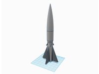
"Tartarus" Model Rocket by HellforgeActual
...parachute storage! = optimized stabilization fins! = 22.5 degree gyroscopic stabilizer fins for straight flight (will provide version without)!...
Lamp
design_connected
$13
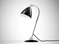
BL2 Table Lamp
...bl2 table lamp
designconnected
gubi bl2 table lamp computer generated 3d model. designed by dudley best , robert .
design_connected
$11
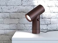
Beam Table Lamp
...beam table lamp
designconnected
muuto beam table lamp computer generated 3d model. designed by chung, tom.
design_connected
$11

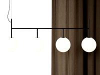
Gravity Floor Lamp
...gravity floor lamp
designconnected
gubi gravity floor lamp computer generated 3d model. designed by space copenhagen.
design_connected
$13

Gravity Table Lamp
...gravity table lamp
designconnected
gubi gravity table lamp computer generated 3d model. designed by space copenhagen.
design_connected
free

JWDA Table Lamp
...jwda table lamp
designconnected
free 3d model of jwda table lamp by menu designed by wagell, jonas.
design_connected
free
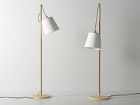
Pull Floor Lamp
...pull floor lamp
designconnected
free 3d model of pull floor lamp by muuto designed by whatswhat.
design_connected
free
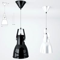
TR Bulb Suspension Lamp
...tr bulb suspension lamp
designconnected
free 3d model of tr bulb suspension lamp by menu designed by rundle, tim.
design_connected
$11

Peek Floor Lamp
...peek floor lamp
designconnected
menu peek floor lamp computer generated 3d model. designed by wagell, jonas.
3d_export
$15
Pendant lamp Original BTC Stirrup Pendant Size 2 3D Model
...al btc stirrup black stainless steel silver
pendant lamp original btc stirrup pendant size 2 3d model pluscreative 90616 3dexport
3d_export
$19
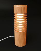
Wooden Lamp01 3D Model
...light vray lighting fixture modern textures materials wooden wood lampshade
wooden lamp01 3d model artem.sheshunov 90503 3dexport