Cults
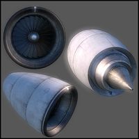
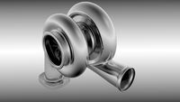
Turboprop Engine
by Cults
Last crawled date: 6 years, 1 month ago
On March 2017, Japanese domestic airplane named YS-11 was retired from about half century service.
YS-11 is equipped the turboprop engine named Rolls Royce "DART".
DART engine series were used Vickers "Viscount744 and 828" and Fokker "F27 Friendship" too in Japan.
Both the models of basic structure and features are the same.
Features of the engine are as follows;
(1) Centrifugal (Impeller type) compressor (2 stages)
(2) Can type Combustion Chamber (7 ea)
(3) Axial Flow Turbine (3 stages)
(4) Reduction gears and propeller shaft (reduction ratio = about 0.1)
(5) Air inlet cowling with Oil Cooler Air Passage
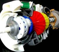
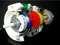
I worked with these engines for long time, therefore I tried to make "Cut-Model" as the memorial model on the desk.
Size and shape of every parts were taken from A4 sized sectional view sheet and some illustrations and pictures at this time.
Download files includes;
-files: STL Files - Sectionalized ZIP
-images: STL File Figure and Index Picture for assembly Aid
Purchase Parts Information;
-Bearings
WBC6-12ZZ (6 x 12 x 4) 6ea - Assemble to outer holes of each Panel ---- Please change these BRG size.---Sorry.
F686ZZ(6 x 1 3x 5) 2ea - Assemble to center of each Panel
689ZZ (9 x 17 x 5) 2ea - For LP and HP Impeller
6900ZZ (10 x 22 x 6) 2ea - For Prop-Shaft, Turbine Shaft
-Aluminum Tubes
9mm dia x Appox. 70mm - as Compressor Rotor Shaft (Make slots both ends)
6mm dia x Appox. 100mm - as Turbine to Compressor Coupling Shaft
-Screws
Micro screws M1.4x3L - Appox. 70 ea - Direct screw-in to 1 mm dia hole (No nut),
Head side flange hole is 1.5 mm dia.
Screws M2 x 20L - 1ea - M2 Tap is used - Starter associate parts
Screws M2 x 10L - Appox. 12ea - M2 Tap is used - Red. Gear Panels associate parts and IGV
Screws M2 x 6L - Appox. 4ea - M2 Tap is used - Diffusers and Turb. Shaft Coupling
Assembly Points
Rotors, Gear Train Set and Casings can be assembled and adjusted separately.
Combustion Air Casing is slid to the outlet elbow assembly until aft end clears from the turbine case its bore at first. Then slide back to bore. Gluing is optional.
Standard Skill (such as Drilling, Tapping, Filing, Tightening, Painting and Gluing etc) is needed and perseverance too.
Total Net Print Time: Approx. 50 HR
(Estimated as case of PLA, 0.4mm Nozzle, 0.2mm Layer Height, 40% infill and No raft and support)
Note: When at actual print, each parameter may be adjusted.
[Update]
I pepared the modified parts and some tools in ;
https://cults3d.com/en/3d-model/tool/turboprop-engine-modified-parts
I pepared the modified parts (No.2) - 2018.1.6
https://cults3d.com/en/3d-model/tool/turboprop-engine-modified-parts-no-2
I prepared the figure for Reduction assembly aid - 2018.1.30.
"01a-Reduction Gear01.jpg"
I pepared the modified parts (No.3) - 2018.2.13
https://cults3d.com/en/3d-model/tool/turboprop-engine-modified-parts-no-3
Before make this, please refer these. Thanks.
YS-11 is equipped the turboprop engine named Rolls Royce "DART".
DART engine series were used Vickers "Viscount744 and 828" and Fokker "F27 Friendship" too in Japan.
Both the models of basic structure and features are the same.
Features of the engine are as follows;
(1) Centrifugal (Impeller type) compressor (2 stages)
(2) Can type Combustion Chamber (7 ea)
(3) Axial Flow Turbine (3 stages)
(4) Reduction gears and propeller shaft (reduction ratio = about 0.1)
(5) Air inlet cowling with Oil Cooler Air Passage
I worked with these engines for long time, therefore I tried to make "Cut-Model" as the memorial model on the desk.
Size and shape of every parts were taken from A4 sized sectional view sheet and some illustrations and pictures at this time.
Download files includes;
-files: STL Files - Sectionalized ZIP
-images: STL File Figure and Index Picture for assembly Aid
Purchase Parts Information;
-Bearings
WBC6-12ZZ (6 x 12 x 4) 6ea - Assemble to outer holes of each Panel ---- Please change these BRG size.---Sorry.
F686ZZ(6 x 1 3x 5) 2ea - Assemble to center of each Panel
689ZZ (9 x 17 x 5) 2ea - For LP and HP Impeller
6900ZZ (10 x 22 x 6) 2ea - For Prop-Shaft, Turbine Shaft
-Aluminum Tubes
9mm dia x Appox. 70mm - as Compressor Rotor Shaft (Make slots both ends)
6mm dia x Appox. 100mm - as Turbine to Compressor Coupling Shaft
-Screws
Micro screws M1.4x3L - Appox. 70 ea - Direct screw-in to 1 mm dia hole (No nut),
Head side flange hole is 1.5 mm dia.
Screws M2 x 20L - 1ea - M2 Tap is used - Starter associate parts
Screws M2 x 10L - Appox. 12ea - M2 Tap is used - Red. Gear Panels associate parts and IGV
Screws M2 x 6L - Appox. 4ea - M2 Tap is used - Diffusers and Turb. Shaft Coupling
Assembly Points
Rotors, Gear Train Set and Casings can be assembled and adjusted separately.
Combustion Air Casing is slid to the outlet elbow assembly until aft end clears from the turbine case its bore at first. Then slide back to bore. Gluing is optional.
Standard Skill (such as Drilling, Tapping, Filing, Tightening, Painting and Gluing etc) is needed and perseverance too.
Total Net Print Time: Approx. 50 HR
(Estimated as case of PLA, 0.4mm Nozzle, 0.2mm Layer Height, 40% infill and No raft and support)
Note: When at actual print, each parameter may be adjusted.
[Update]
I pepared the modified parts and some tools in ;
https://cults3d.com/en/3d-model/tool/turboprop-engine-modified-parts
I pepared the modified parts (No.2) - 2018.1.6
https://cults3d.com/en/3d-model/tool/turboprop-engine-modified-parts-no-2
I prepared the figure for Reduction assembly aid - 2018.1.30.
"01a-Reduction Gear01.jpg"
I pepared the modified parts (No.3) - 2018.2.13
https://cults3d.com/en/3d-model/tool/turboprop-engine-modified-parts-no-3
Before make this, please refer these. Thanks.
Similar models
thingiverse
free
Turboprop Engine by konchan77
...flange-screw01" figure added about m1.4 screw.
[update]20201018
add "shaft-coupling 101.stl" having thicker wall.
cults
free

Turboprop Engine Modified Parts (No.3)
...ecommended.
still this is not the model to print and assemble easily, i hope your perseverance too.
thank you for your interest.
cults
$16

Turboprop Engine, for Business Aircraft, Free Turbine Type, Cutaway
...m in the creations which i made before.
i do hope your success!!
[update] - 2018.3.14
photo of typical special support is added.
cults
$10

Turboprop Engine, for Business Aircraft, Cutaway
... hope your success!!
[update 2017.12.15]
for "dummy propeller assy", related stl files (4), photo and image are added.
thingiverse
free

Turboprop Engine Modified Parts by konchan77
...hp rotor clearance parts shape is changed to more similar to actual parts. [new] impeller-hp101: add slots on back...
cults
free

Turboprop Engine Modified Parts
...urbine rotor to shaft
this is not the model to print and assemble easily, i hope your perseverance.
thank you for your interest.
cults
$5

Jet Engine, Single-Spool with AfterBurner
...
price discount
[update 2017.12.14]
for "non-shrouded turbine blades rotor", stl file (3), photo and image are added.
cults
free

Turboprop Engine Modified Parts (No.2)
...as possible.
still this is not the model to print and assemble easily, i hope your perseverance too.
thank you for your interest.
grabcad
free

Impeller
...impeller
grabcad
centrifugal compressor impeller.
single entry impeller for gas turbine engine
thingiverse
free

Turboprop Engine Modified Parts (No.3) by konchan77
...recommended.
still this is not the model to print and assemble easily, i hope your perseverance too.
thank you for your interest.
Turboprop
3d_export
$40

Turboprop twin engine 3D Model
...boprop twin engine plane airplane civilian commercial passenger medium range
turboprop twin engine 3d model tartino 7205 3dexport
cg_studio
$380

Antonov bureau AN-24 RV Aeroflot3d model
...bureau an24 an-24 rv an24-rv an-24-rv transport airport russia turboprop .max - antonov bureau an-24 rv aeroflot 3d model,...
3d_ocean
$25

Socata TBM 900 aircraft
...the tbm850 and tbm900) is a high performance single-engine turboprop light business and utility aircraft manufactured by socata. an...
3d_ocean
$25

Cessna citation 510 mustang
...cessna mustang civil aviation jet light aircraft small jet turboprop engine aircraft high detailed cessna citation 510 mustang civial...
cg_studio
$120

Bristol Britannia3d model
...bristol britannia3d model cgstudio aircraft bristol britannia turboprop monarch airplane airliner 1950 propeller commercial airline .3ds .c4d...
cg_studio
$100
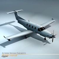
Pilatus PC-123d model
...pilatus pc-123d model cgstudio aircraft pilatus pc12 pc 12 turboprop plane airplane .3ds .c4d .dxf .obj - pilatus pc-12...
3d_ocean
$19

Beech craft King Air 350 propeller aircraft
...flying kingair livery passengers private propeller sport transport transportation twin-turboprop 3d model created with blender3d 2.76 version.renderings with blender...
3d_ocean
$19

Beechcraft Starship 2000 aircraft concept
...flying landing passenger plane private propeller sport starship transportation twin-turboprop pretty futuristic and original twin-turboprop concept by beechcraft aircraft...
cg_studio
$40

Turboprop twin engine3d model
...er medium range
.3ds .c4d .obj - turboprop twin engine 3d model, royalty free license available, instant download after purchase.
3d_export
$59
Pilatus PC9 3D Model
...pilatus pc9 3d model 3dexport high poly pilatus pc turboprop pilatus pc9 3d model kierancrayn43529 32068...
Turbine
cg_studio
$15

Low Poly Wild West Wind Mill3d model
...construction energy health country village metal wings ecology eco turbine generator power electricity .fbx .3ds .max .obj - low...
3d_export
$10

Wind Turbine 3D Model
... hawt horizontal axis electric
wind turbine 3d model download .c4d .max .obj .fbx .ma .lwo .3ds .3dm .stl firdz3d 107121 3dexport
cg_studio
free
Jet engine FREE3d model
...pratt military air jet motor turbo airplane blades propeller turbine fly plane gas .max - jet engine free 3d...
3d_ocean
$5

Wind turbine
...ready to import and render in all formats, it being a valuable prop for any render. for other cool stuff check out my sales. e...
3d_ocean
$12
Retro Plastic Fan with Render Setup
...blade blower cool cooling desk desktop fan plug propeller turbine vent ventilation ventilator wire small desktop fan with wire,...
3d_ocean
$8
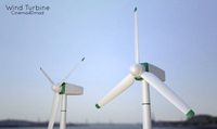
Wind Turbine
...of cinema4d r13. 3 different files included :wind turbine :wind turbine.obj :window turbine render set up the hdri/background ...
3d_ocean
$5
Aircraft Turbine
...ly count: 1828 polys - formats: max /obj /fbx - high detail was preserved with 2048×2048 textures - maps included ( all in 204...
3d_ocean
$6

Aircraft Open Turbine
... - poly count: 2687 polys - formats: max /obj /fbx - high detail was preserved with 2048×2048 textures - maps included ( all i...
3d_ocean
$5
Turbocharger
...engine exhaust forced garrett induction intake precision racing supercharger turbine turbo turbocharger turbonetics wheel a turbocharger model built to...
3d_ocean
$4

Wind Turbine
...n
and render setup turbine wind
wind turbine, modeled with cinema4d r13 , render setup and textured, custom logo for wind turbine
Jet
3d_export
$85
JAS 39 Gripen Jet 3D Model
...ipen jet 3d model
3dexport
aircraft airplane fighter military attack jet
jas 39 gripen jet 3d model vanishingpoint 72995 3dexport
3d_export
$65
News Helicopter 3D Model
...news helicopter 3d model 3dexport aircraft airplane commercial jet airliner civilian flight vehicle transportation helicopter news r44 news...
3d_export
$40

Cessna citation cj4 3D Model
...cessna citation cj4 3d model 3dexport airplane jet aircraft bussines plane private civilian wings cessna citation cj4...
3d_export
$95

Falcon3D A319 United Airlines 2 3D Model
...airplane aircraft airliner plane transport commercial passenger modern twin jet civil civilian a320 a321 a318 a319 airbus falcon3d a319...
3d_export
$95

Falcon3D A340 600 Pacific Charters 3D Model
...plane transport commercial passenger modern twin jet civil civilian jetiner a340 a-340 a-340-600 a340-600 airbus falcon3d a340 600 pacific...
3d_export
$95
Falcon3D MD 80 Hawaiian 3D Model
...freight cargo corporate mcdonnell douglas us plane planes jet jetiner md-80 falcon3d md 80 hawaiian 3d model falcon3d 73148...
3d_export
$65
Aircraft 737 3D Model
...aircraft 737 3d model 3dexport aircraft airplane commercial jet airliner civilian flight vehicle transportation aircraft 737 3d model...
3d_export
$95
Falcon3D MD 80 Fast Cargo 3D Model
...freight cargo corporate mcdonnell douglas us plane planes jet jetiner md-80 falcon3d md 80 fast cargo 3d model falcon3d...
3d_export
$50
Bell 407 Jetranger 3D Model
...e commercial jet airliner civilian flight vehicle transportation helicopter
bell 407 jetranger 3d model digimation 73228 3dexport
3d_export
$85
Tempest 3D Model
...tempest 3d model 3dexport aircraft airplane fighter military attack jet british england raf tempest 3d model vanishingpoint 73000...
Engine
3d_export
$10

Wooden Pallet Low Poly 3D Model
...props lowpoly industrial wood 3d unity udk unreal games engine detailed wooden wooden pallet low poly 3d model turcpaul...
3d_export
$10

Old Pallet Low Poly 3D Model
...lowpoly industrial wood old 3d unity udk unreal games engine detailed fbx obg 3ds old pallet low poly 3d...
3d_export
$40
Turboprop twin engine 3D Model
...boprop twin engine plane airplane civilian commercial passenger medium range
turboprop twin engine 3d model tartino 7205 3dexport
3d_export
$29

Female cyborg 3D Model
...bot machine female woman bionic metalic android human science enginering technology future metal fantasy technics sci-fi female cyborg 3d...
3d_export
$75
Falcon3D C414 Chancellor Bare Metal 3D Model
...civil general aviation executive transport charter professional place twin engine propeller commercial ambulance falcon3d c414 chancellor bare metal 3d...
3d_export
$85
Falcon3D C414 Chancellor F02 3D Model
...civil general aviation executive transport charter professional place twin engine propeller commercial ambulance falcon3d c414 chancellor f02 3d model...
3d_export
$15
Classic Steam Train 3D Model
...steam train 3d model 3dexport antique black classic coal engine historic historical iron locomotive metal old power rail railroad...
3d_export
$45
4 Bearing Collection 3D Model
...ballbearing roller ball tapered bearing skf needle engineering gearbox engine car industrial thrust spherical radial machinery race cage collection...
3d_export
$100

2011 Hyundai Verna 3D Model
...hyundai verna sonata tucson avante tuscani genesis gamma gasoline engine coupe sports korean 3dken 2011 hyundai verna 3d model...
3d_ocean
$69
T-34/85 Interior/Engine Bay Full Winter Camo
...nterior and engine bay. the model contains a highly detailed interior(controls, gauges, machine gun, ammo, radio, main gun) an...