CG Trader

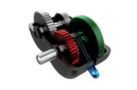
Electrically shifted gearbox
by CG Trader
Last crawled date: 1 year, 10 months ago
Schematic of an electrically shifted gearbox. The gearbox works by connecting one of the orange gears with the output shaft. The orange gears are already connected to a gear fixed on the layshaft, in turn connected to the input shaft, so the closing of the connection to the output shaft will relay the power to the wheels. The connecting is done by means of an electrically-powered internal cone, which, when triggered connects to the external cone. The shifting works as follows: * One of the buttons on the control panel is pressed * The switchboard, connected to this control panel, and with the battery, and 4 wires of which one pair always leads to the internal cone, creates a circuit where a current is passed to a internal cone/synchronizer sleeve. This creates a positive or a negative charge on the internal cone, making it being pulled towards the positive or negative magnet. There is also a sensor placed on the two internal cones, powered by the battery . And there is also a dotted circle on the outside of the nearby orange gear. This makes sure the attraction is initiated at exactly the right moment. The attracting is done in two steps, at first minor attraction occurs -> to slide the parts side-by-side, after which a rapid attraction is done. It should also be mentioned that the shafts are not made in metal, else they would be detrimental for the magnets. Finally, if the 1st shaft rotates the fastest, the internal cones are best put on the second axle
Similar models
3dwarehouse
free

Electrically shifted gearbox
...be detrimental for the magnets. finally, if the 1st shaft rotates the fastest, the internal cones are best put on the second axle
cg_trader
$20

Standard gearbox | 3D
...eeve, external cone & drive dogs. gearbox gearstick gears vehicle shift hobby diy hobby diy mechanical parts mechanical parts
3dwarehouse
free

'Schematic of a manual (or standard) gearbox'
...ernal cone, synchronizer sleeve, external cone & drive dogs. #3d #appropedia #gearbox #manual #model #schematic #transmission
cg_trader
$46

IC motor transmission | 3D
...l information on the model transmission internal combustion motor mechanics hobby diy hobby diy mechanical parts mechanical parts
grabcad
free

2-speed gearbox
...a reducer with the first combination (z1=60 m=1 z2=100 m=1)
and as an icreaser with the second combination (z3=45 m=2 z4=35 m=2)
grabcad
free

Long Tail Boat Gearbox (with Internal Gear)
...e shaft of the engine and the ring gear is connected to the propeller shaft, the propeller fan is fitted in this propeller shaft.
cg_trader
$5
2-speed gearbox | 3D
...educer gearbox tooth transfer 2012 manual clutch transmission vehicle other hobby diy hobby diy mechanical parts mechanical parts
grabcad
free

Power Take Off
...xample, the front output can be used for a drive train, while the other shaft can be used for an auxiliary system such as a lift.
grabcad
free

GearBox
... cylindrical with m=1 , no of teeth - 17
gear ot shaft 3: cylindrical no of teeth - 67
output torque: 10 nm
output speed: 305 rpm
grabcad
free

Planetary Gearbox #347 | design with ajay |
... ratios. they are widely used in a variety of applications, including automobiles, industrial equipment, robotics, and aerospace.
Shifted
3ddd
$1

Термостат Jacob Delafon Aparu E9113-CP для ванны с душем
.../shop/product/24675 http://santehnika-online.ru/product/dushevaya_leyka_jacob_delafon_shift_ellipse_e10257_cp/
3ddd
$1

RH MODERN DESMOND BEDROOM SET
...san crafted and no two are alike. given their handwoven nature, slight variations in shading and size are inherent to the design.
3ddd
free

новогоднее украшение
...авиатура. шифт +ай (shift+i)
2 активируем кнопку pick path
3наводим на сплайн и кликаем, количество клонов в первой шкале.
удачи.
3ddd
free
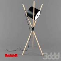
Artisan-Shift lamp
...ovak-mikulić & marija ružić
rods diameter: ø 2,7cm
base: 70 x 70 cm
height when assembled: 200 cm
model have three frames.
3ddd
$1

Pastoe \ Shift
...pastoe \ shift
3ddd
pastoe , тумба
современная тумба от фабрики "pastoe"
3ddd
free

Shift Lamp
...amp
3ddd
artisan , shift
http://www.artisan.ba/en/products#collection/shift/69
3ddd
$1

Унитаз и биде Vitra Shift
...catalog.vitra-russia.ru/products/matovyi-hrom-panel-sistemy-smyva-s-mehanicheskimi-knopkami-panel-upravleniya-dvoinaya/
3ddd
free

45°/TAVOLINO
...lue reiterates the basic shapes
that characterize the collection. elements of pure light that appear to suggest hidden treasures.
3ddd
$1

45°/TAVOLO
...ft that moves from an angle of 90°
to one of 45° without corners. elements of pure
light that appear to suggest hidden treasures.
cg_studio
$25

Bicycle Chain Heart3d model
...wo .igs .dwg .c4d .max .3ds .3dm - bicycle chain heart 3d model, royalty free license available, instant download after purchase.
Gearbox
3d_export
$45
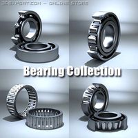
4 Bearing Collection 3D Model
...bearings ballbearing roller ball tapered bearing skf needle engineering gearbox engine car industrial thrust spherical radial machinery race cage...
3d_ocean
$3

Gears 4
...clock gear clockwork cog cogwheel customizable engine factory gear gearbox gears gearset gearwheel industrial parts industry machine machine gears...
3d_ocean
$99
Full Land Rover Defender 90 Hard Top
...with a highly detailed interior and chassis, with engine, gearbox exhaust, suspension and brakes modeled. the model comes in...
3d_ocean
$12

Exploded Half Axle
...half axle 3docean axle chassis constant cv drive engine gearbox joint part planetary shaft velocity wheel an exploded half...
3d_ocean
$35

Pzkpf I Ausf B
...the six cylinder water cooled engine and more reliable gearbox tracks are...
3d_ocean
$3
Ball bearing
...ball bearing 3docean ball bearing bearings car gearbox high industrial machine parts poly radial vehicle wheel a...
3d_ocean
$3

Planetary gears
...planetary gears 3docean automatic car cogs differential drive engine gearbox gears gearset manual mechanical planetary power sprocket a set...
3d_ocean
$99

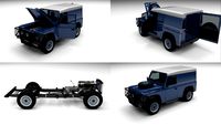
Full Land Rover Defender 110 Double Cab Pick Up
...with a highly detailed interior and chassis, with engine, gearbox exhaust, suspension and brakes modeled. the model comes in...
3d_ocean
$99

Full Land Rover Defender 110 Utility Station Wagon
...with a highly detailed interior and chassis, with engine, gearbox exhaust, suspension and brakes modeled. the model comes...
3d_ocean
$3

Gears 2
...clock gear clockwork cog cogwheel customizable engine factory gear gearbox gears gearset gearwheel industrial parts industry machine machine gears...
Electrically
3d_export
$37

Horseshoe Electric Guitar 3D Model
...horseshoe electric guitar 3d model
3dexport
horshoe guitar
horseshoe electric guitar 3d model nikkistinger19 38426 3dexport
3d_export
$20

2010 Toyota Rav4 EV 3D Model
...lowpoly automobile suv cuv american gm real time realtime traffic game hybrid
2010 toyota rav4 ev 3d model be_fast 30762 3dexport
3d_export
$6

Philishave electric shaver 3D Model
...odel
3dexport
philishave shave shaving electric shaver hair cutter
philishave electric shaver 3d model medesdesign 49599 3dexport
3d_export
$15

Blender 3D Model
... electric home dining mixer juicer mixing chef grinder restaurant cookware food household
blender 3d model firdz3d 84495 3dexport
3d_export
$5

Buld 3D Model
...rn candle illumination streetlight electric light bulb incandescent filament lamp glow-lamp inc
buld 3d model kiko 50448 3dexport
3d_export
$20
Old radio 3D Model
...reo hifi mono sound volume voice audio electric electronics orchestra music antique
old radio 3d model jovicalokin 68737 3dexport
3d_ocean
$3

Schuko Socket
...nector power power point safety socket schuko socket wall socket
a schuko socket like the ones used in germany. colored old white
3d_ocean
$12
Wheel Smart Electric Scooter
...in vray 1.5. autodesk 3d max 2009 file mb contains all vray materials and render setup. the model is suitable for extream high...
3d_ocean
$22
Electric Grill
...el of black electric grill. available formats: • max scanline • max vray • max mentalray • cinema 4d • cinema 4d vray • fbx • obj
3d_ocean
$35
Elevator Lift 3D Model produced by OTIS
...eel & glass for people transport. ready to render for: - maxwell render 2.0 standalone or higher - 3ds max 2008 + maxwell ...