GrabCAD
NASA EAS - Final Update
by GrabCAD
Last crawled date: 1 year, 10 months ago
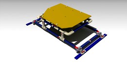
NASA Experiment Attachement System - EAS
https://grabcad.com/challenges/nasa-experiment-attachment-system-eas-challenge
At first I would like to thank NASA for bringing this challenge ( perhaps much more in the future ) and allowing me be part of this endeavor.
Here are some considerations and reasons of my design:
1- My main goal was create a system easy to use, with minimum number of assembly steps in orbit. 2 sub-assembly was the objective. And line-up the design with main goal of the NASA Logistics Reduction.
2-Avoid the use of sheet metal. The reason sheet metal under stress exhibit local buckling, and this is very hard to detect without using a buckling FEA model. Sheet metals have another problem: After laser cutting, the edges are sharp and you need do rework on that, increasing the cost.
3-Reduce to minimum the use of metals with complex form. The reason for that is that with the increase in complexity of the part, it is less likely to be reused in other way, since the complex geometry don't allow that. Because of that i decided use the same external profile as the handrails of the previous NASA challenge ( https://grabcad.com/challenges/nasa-handrail-clamp-assembly-challenge ), allowing other use after the end of experiment.
4-Since I am using the handrails, it is possible to modify in order to get other EAS geometry for other future experiments? The ABS joins allow easy customization, with the R3DO and AMF, it is possible to produce these parts inside the ISS. Just been necessary launch new rails for the structure. This way reducing the weight in future missions.
5-The surface interface with the seat track was designed wide to reduce the moments and convert it to force. Hand calculations showed that force limits wouldn't be a problem, but the moment would be. A self-lock system was placed for the purpose of reducing the use of tools.
6-I didn't add the threaded inserts for the abs parts in the .step, the reason I wouldn't be able to model the interaction of the insert and the abs.
7-If necessary i can upload the results for the orthogonal load after the deadline in the comments. FOS was 2,29 for this load.
8-It is possible to change the materials of handrails to one with less tensile strength, since the highest von-misses stress happens in the pins. But the Young´s modulus should be close in order to keep secondary stress effects in check.
9-The contact adopted in the FEA simulations was frictionless. This type of contact allow that the distance between parts change with the time, but don't allow one part to go inside the other. I tried to reproduce the best of the real system, but this had a cost in processing time, when compared with one-piece model.
10-It wast possible to perform a mesh convergence analysis due the insufficient memory of my workstation.
Judging criteria:
Description of system : OK
STEP/IGES: OK
Assembly Procedure: OK
Sharp Human edge criteria : OK
Factor of Safety: OK
Deflection: OK
Force and Moment Reactions: OK
EAS Envelopoe: OK
Launch Envelope : OK
Mass: OK
Materials : OK
Captive fasteners, retaining pins: OK
Similar models
grabcad
free

EAS_FNDK
...eas_fndk
grabcad
nasa experiment attachment system (eas) challenge. no need screew mouting. easy assembly.
grabcad
free

Nasa Experiment - Sheet Metal brackets
...t easily resist to applied forces and will be stiff (no play between components).
- captive hardware (no parts to lose in space!)
grabcad
free

NASA Handrail
...nasa handrail
grabcad
handrail for the https://grabcad.com/challenges/nasa-handrail-clamp-assembly-challenge
timesaver
grabcad
free

NASA Handrail Clamp Assembly Challenge
...nasa handrail clamp assembly challenge
grabcad
nasa handrail clamp assembly
grabcad
free

NASAEAS
...cad
this is my entry for this amazing challenge :
https://grabcad.com/challenges/nasa-experiment-attachment-system-eas-challenge
grabcad
free

Nasa Handrail clamp Assembly
...
material: palstic
there are in this assembly 6 part.
for all step/iges and stl file.
i am very happy somethnig for nasa modeled.
grabcad
free

NASA handrail clamp
...assembly parts are not loose. clamp is possible to operate by one hand. clamps fastening force by eccentric pivot axle of handle.
grabcad
free

Test handrail for the NASA Handrail Clamp Assembly Challenge
...o warranty on correctness!).
it is designed as a solid for better stiffness and strength.
100 mm long
print with min. 15% infill
thingiverse
free

Test handrail for the NASA Handrail Clamp Assembly Challenge by 3dDruckIng
...no warranty on correctness!).
it is designed as a solid for better stiffness and strength.
100 mm long
print with min. 15% infill
grabcad
free

Challenge - Nasa Handrail Clamp
...
i don't have any experience on 3d printing, so i hope it works! i had a lot of fun making this model for the challenge! =)
Eas
3ddd
$1

Aluminium Chair EA 124
...luminium chair ea 124
3ddd
vitra
материалы corona
сайт производителяhttp://www.vitra.com/
габариты кресла 985х650х780
3ddd
$1
Soft Pad Group EA 215 EA 216
...ay eames
launched in 1969
920 x 620 x 720 mmhttp://www.architonic.com/pmsht/soft-pad-group-ea-215-ea-216-vitra/1003343
3d_ocean
$5

Freestanding, Modern Bathtub_No_26
...op into any scene or be used as a stand-alone prop. material setup is not included. professional quality model designed for ea...
3d_ocean
$5

Freestanding, Modern Bathtub_No_07
...op into any scene or be used as a stand-alone prop. material setup is not included. professional quality model designed for ea...
3d_ocean
$5
Coffee cups (scene included)
...ready to render (includes detailed,textured 2 coffee cups, lighting / texturing setup, render settings and post production -ea...
3d_ocean
$5

Freestanding, Modern Bathtub_No_18
...op into any scene or be used as a stand-alone prop. material setup is not included. professional quality model designed for ea...
3d_ocean
$5

Freestanding, Modern Bathtub_No_15
...op into any scene or be used as a stand-alone prop. material setup is not included. professional quality model designed for ea...
3d_ocean
$5

Freestanding, Modern Bathtub_No_03
...op into any scene or be used as a stand-alone prop. material setup is not included. professional quality model designed for ea...
3d_ocean
$5

Freestanding, Modern Bathtub_No_16
...op into any scene or be used as a stand-alone prop. material setup is not included. professional quality model designed for ea...
3d_ocean
$5

Freestanding, Modern Bathtub_No_12
...op into any scene or be used as a stand-alone prop. material setup is not included. professional quality model designed for ea...
Nasa
3d_ocean
$15
Stratosphere HDRI
...astronaut earth emu eva eva missions hdr hdri highres nasa outer space panorama planet refraction skydome space spaceship stars...
3d_ocean
$9

HD Earth Model
...hd earth model 3docean atmosphere clouds earth mars moon nasa ocean photorealistic planet poly realistic rock sky solar space...
3d_ocean
$9
Realistic HD Earth Model
...earth model 3docean 3dmodel atmosphere clouds earth mars moon nasa ocean photorealistic plane poly realistic rock sky solar stars...
3d_ocean
$29

Spaceship Progress Soyuz
...spaceship progress soyuz 3docean 3d cosmos iss launch mir nasa orbital rocket russian satellite ship solar space spacecraft sputnik...
3d_ocean
$5

Sun Model
...sun model 3docean atmosphere clouds mars moon nasa ocean photorealistic planet poly realistic rock sky solar space...
3d_ocean
$49
New Horizons Space Probe
...3docean astronomy astrophysics c4d cinema 4d element 3d mission nasa new horizons obj pluto satellite space space probe spacecraft...
3d_ocean
$3

Sun
...sun 3docean cosmos earth galaxy milky moon nasa planet sky space sun system universe a sun model...
3d_ocean
$6

HD Saturn Model
...hd saturn model 3docean atmosphere clouds mars moon nasa ocean photorealistic planet poly realistic rock saturn sky solar...
3d_ocean
$5
Uranus Model
...uranus model 3docean atmosphere clouds mars moon nasa ocean photorealistic planet poly realistic rock sky solar space...
3d_ocean
$12

Photoreal Earth Model
...earth model 3docean atmosphere clouds continent earth globe iss nasa ocean orbit planet science space terra turkey usa 21k...
Final
3d_ocean
$7

Romantic rose
...red romatic rose 3d model: romantic rose 3d model final render and setting global illumination with cinema 4d include...
3ddd
$1
Настольная лампа Hampton
...3ddd hampton lighting , venetain настольная лампа hampton venetain final max2014...
3ddd
$1
Dalyan Barchair by Brabbu
...leather of this home furniture piece will give the final touch to every project. product features fabric: synthetic leather...
cg_studio
$10

Golden Champion Cup Winner 23d model
...cgstudio cup golden gold trophy sport award champion super final medal league prize winner victory household memory .obj .fbx...
3ddd
$1
Wegner and Paul Smith Shell Chair
...1997 and after 34 years of oblivion the chair finaly got its breakthrough. as a curiosity, it is worth...
cg_studio
$19

Basketball Trophy3d model
...basket usa trophy ball gold award champion super cup final medal league prize winner victory .3ds .obj .fbx .max...
3ddd
$1

wood screen
...add turbo-smooth to the model in obj file. - finaly ... thank you and i hope model be useful...
3d_ocean
$2

Maya mental ray mib_occlusion material settings
...mental ray mib_occlusion material. no gi, no lights, only final ...
3d_ocean
$2
gae bolg animus
...gae bolg animus 3docean animus bolg fantasy ffxiv final fantasy final fantasy xiv gae gae bolg animus weapon...
3d_ocean
$15

Nokia 635 green
...the 3ds max format includes vray material . the final images of the thumbnails have been created with the...
Update
3d_ocean
$15
Selling 3D Models True Secrets of 3D Artists book
...to turbosquid vray updated to version 1.1 at 07.12.2015, update includes: - whole book re-edited to better reading -...
3ddd
$1
Vintage Fan & Suitcases
...есть отдельная библиотека материалов (для быстрой смены материалов используйте update scene materials from library). для металлов в канале отражений...
3d_ocean
$9

Colorful balloons
...have any questions about my items or want to update to this item after the selling, please contact me....
3d_ocean
$12
20 Wood Floor Planks - Truffle
...3docean residence ted todd truffle wood floor plank textures update! based on feedback the lighting variation on some of...
3d_ocean
$10
Photorealistic Jewelry Render Pack for V-Ray
...tomislavn topaz v-ray vray white gold zircon 25.09.2013. free update for all buyers | includes better lightning and materials...
3d_ocean
$8

Nike Ordem 2 Official Match Ball
...liga league nike official ordem premier serie a soccer update! nike ordem 2 soccer ball for the next season....
3d_ocean
$12
Bags And Box Vray - (C4D)
...3ds. c4d. dxf. obj. needs plugin for c4d: http://www.codeworkers.de/garage-plugins-reeperx.html update added. “happy meal...
3d_ocean
$2

Low Poly Pine Tree
...have any questions about my items or want to update to this item after the selling,...
3d_ocean
$19

Element3D - Apple Macbook Pro Retina
...laptop mac macbook notebook retina screen thunderbolt tomislavn 22.09.2014. update model! added speaker grid and some more detailed textures...
3d_ocean
$55

V-Ray Render Setup Collection 1-5
...render setups from 1 to 5, with all new update support for older 3dsmax versions starting from 2011 and...