GrabCAD
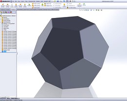
How to model a Dodecahedron from scratch
by GrabCAD
Last crawled date: 1 year, 10 months ago
Using a surface part to form an assembly that is turned into a solid object - no sweat or mathematics required. Download all the step-by-step screendumps if you want to follow the build on screen.
1) Draw a sketch of a pentagon (Step1.jpg)
2) Create a planar surface body from the sketch (Step2.jpg)
3) Save as a part file (Step3.jpg)
4) Use the function "Create Assembly From Part" (Step4.jpg)
5) Click the green check mark to insert and fix the pentagon in the assembly (Step5.jpg)
6) Control-drag a copy of the pentagon into the assembly from the feature tree (Step6.jpg)
7) Orient it so that two edges are close to each other (Step7.jpg)
8) Mate the two edges with a coincident relation (Quickest way is to control-select both and choose the mate-icon from the pop-up menu) (Step8.jpg and Step9.jpg)
9) Control-drag another copy of the pentagon into the assembly (Step10.jpg)
10) Mate it to one edge on the fixed pentagon and one edge on the movable pentagon. This fully defines the model (Step11.jpg and Step12.jpg)
11) Control-drag the next three pentagons into the assembly and constrain their edges with coincident mates (Step13.jpg and Step14.jpg and Step15.jpg)
12) Inserting the last piece will probably over-define the assembly. This warning is not critical, but you can make it disappear by deleting a mate, if you wish.
13) Highlight and right-click all the parts in the feature tree and select the function: "Form New Subassembly Here". This allows us to save time and sweat by reusing existing geometry (Step16.jpg)
14) Control-drag a copy of the new subassembly into the assembly (Step17.jpg)
15) Orient it so that it matches the fixed part (Step18.jpg)
16) Mate three sets of corner points to each other to fully define the model. You have now created an assembly with a surface model of a dodecahedron (Step19.jpg)
17) Save the assembly as a PART file with the option "Exterior Faces" selected. You don't need to save the assembly itself as it's just an intermediate model (Step20.jpg)
18) Open the part file you just saved (Step21.jpg and Step22.jpg)
19) Use "Knit Surface" with the "Try to form solid" option selected while selecting all 12 surfaces from the Surface folder in the feature tree, to turn this surface model into a solid model (Step23.jpg)
20) Select all external surfaces and apply a Fillet of 1 mm (Step24.jpg and Step 25.jpg)
21) You have created the solid dodecahedron without sweat or mathematics ;-)
Similar models
grabcad
free

Bobcat Loader with solid works
...er with solid works
grabcad
bobcat loader with solid works
parts
subassemblies
full assembly
render
step files
solid works files
grabcad
free

Cooking Pot
...ok at on the mate of the parts "bağ" and "tencere" in assembly file and the parts' dimensions and planes.
3dwarehouse
free

Dodecahedron
...
one of the five regular solids, constructed from a pentagon by the compass-and-straightedge method #dodecahedron #solid_geometry
grabcad
free

Request: Beam column end-plate connection
... do a 3d sketch to locate holes
7.- do settings
8.- on tool box, select the screw and drag it to hole
9.- do settings
10.- finish
3dwarehouse
free

Great Dodecahedron
...doing a succession of rotate/copy on the edges. 63.43 degrees. it required changing around the axes a whole bunch but it was fun.
grabcad
free

Scissor lift assembly
...dent mates for the base piece
3. concentric mate for circular pieces
4. plunger distance mate
5. pin mates for any leftover holes
grabcad
free

v12 Engine
...v12 engine
grabcad
full v12 engine assembly with 380 parts, 185 mates, and 60 subassemblies
cg_trader
$10

Dual Checkerboard Dodecahedron | 3D
... remeshing to a quasi-regular polyhedron. a perfect object for 3d printing as a mathematical showpiece, or a unique fidget toy.
grabcad
free

Five cubes in a dodecahedron
...n
grabcad
five cubes in a dodecahedron
my first attempt at modelling solids from
mathematical models
cundy and rollett (1960)
3dwarehouse
free

Dodecahedron
... meeting at each vertex. it has 20 vertices and 30 edges. (source: wikipedia) #dodecahedron #geometry #platonic_solid #polyhedron
Dodecahedron
3d_ocean
$14

Decorations Set
...set 3docean concrete contemporary coral deco decoration design designer dodecahedron flower gold interior leaf leaves living marble modern origami...
3ddd
$1
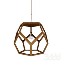
Dustin Dodecahedron by Ralph Lauren
... from circa lighting.http://www.houzz.com/photos/2389670/large-dustin-dodecahedron-wood-pendant-modern-pendant-lighting
3d_export
$26

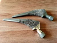
Spider decorated shield 3D Model
...spider decorated shield 3d model 3dexport web spider dodecahedron shield poly low handles two military weapons low-poly textured...
3d_export
$5
tibia implant real model for training
...porosity: the name of the porosity element is a dodecahedron the size of the porosity element is 1.5×1.5×1.5 mm...
3d_export
$14

Escher Spheres animated
...tetrakis hexahedron<br>lizards sphere - rhombic dodecahedron<br>fishes sphere - regular dodecahedronlt;br>[video=https://sketchfab.com/marcosfaci/models] ...
turbosquid
$5

Dodecahedron Tetartoid
...alty free 3d model dodecahedron tetartoid for download as stl on turbosquid: 3d models for games, architecture, videos. (1433097)
turbosquid
free

Flower pot dodecahedron with saucer base
...er base for download as skp, stl, dwg, dxf, fbx, ige, and obj on turbosquid: 3d models for games, architecture, videos. (1626531)
turbosquid
free

Flower pot dodecahedron with saucer base
...se for download as ipt, skp, obj, stl, dwg, dxf, fbx, and ige on turbosquid: 3d models for games, architecture, videos. (1708431)
turbosquid
$60

Dodecahedron Wonder
...
royalty free 3d model dodecahedro wonder for download as stl on turbosquid: 3d models for games, architecture, videos. (1460578)
turbosquid
$6

Dodecahedron Deco Geometric Decor Ball
...decor ball for download as obj, wrl, fbx, blend, dae, and stl on turbosquid: 3d models for games, architecture, videos. (1374307)
Scratch
3d_ocean
$19
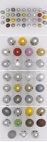
34 metal shaders
...come in different styles like brass, scratched, dirty, blurred. scratchs *.vismat materials files are all included in the main...
3d_ocean
$5
Metal Textures 004
...copper corrosion glossy gold iron medieval metal rust satin scratch seamless silver stainless steel sword texture tileable metal textures...
3d_export
$39

Sea Container bookcase 3D Model
...3d model 3dexport iron bookcase rough sea container loft scratch black seam old weathered industrial style sea container bookcase...
3ddd
$1

Индустриальный Светильник | Industrial Lighting
..., подвесной индустриальный светильник. для бампа использовался плагин "siger scratchs"http://www.sigerstudio.eu/shop/plugins-free/sigertexmaps-sigerscratches/ ...
3ddd
$1

Poltrona Frau JOBS
...the interior frame is painted black with a texturized, non-scratch finish. on the side opposite the drawer, known as...
3ddd
$1

Cappellini / SCRATCH
...cappellini / scratch
3ddd
cappellini
www.cappellini.it
3ddd
$1
15 Metal Material For VRay
...this is 15 useful metal material for vray 5 scratch texture + 5 normal map i create 35 image...
3d_ocean
$6
12 Gold Materials
...- shiny gold - brass gold - scratched gold scratch... ...
3ddd
$1
Pioneer DJM-707
...a 3d model of dj mixer pretty good for scratchng. hope it will come handy for...
3d_ocean
$8

Garbage Bin
...trash trashcan model of a metal garbage bin with scratchs. made in cinema 4d. files included: .c4d .3ds...
How
3d_ocean
$15

Selling 3D Models True Secrets of 3D Artists book
...3docean 3d bill bills book cover dollar dollars ebook how make models money on online preset render sell selling...
3d_ocean
$6
32 Leather Materials Pack
...texture ready to used, best for sofa. include instruction how to instal it. format : - .lib4d thank you...
3ddd
$1

Vitra / How High the Moon
...ow high the moon" японского дизайнера shiro kuramata для vitra, 1986 год.
материал - вытяжная сетка из никелированной стали.
3ddd
$1

Dalyan Barchair by Brabbu
...bar chair product description if cleopatra was alive today, how would it be the furniture of her palace? that...
3ddd
$1
Tractor Barstool
...the side of the road. he was impressed by how the seat allowed him to sit in an upright,...
3ddd
$1

Sokoa K01
...the manufacturing of 35 interdependent moulds achieved with the know-how of one of the world's best injector. at the...
3ddd
free

Ginger & Jagger Earth To Earth тумба и шкаф
...литой латуни nature has a way of inspiring creativity. how far would you go for...
3d_ocean
$4
Column Texture
...also provided… so that you can tile the image how you like -easy to...
3d_ocean
$5

Swivel Flashdisk - Black
...rendered in blender 2.71 if you want to see how i make this 3d model watch it in here...
3d_ocean
$20
Sea scene Amazing sea material
...seen in the preview (fully animated) details insruction showing how to...