GrabCAD

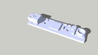
Pressure Sensor SPC01B1A
by GrabCAD
Last crawled date: 1 year, 10 months ago
Enclosure:
The assemble printed circuits fits in a small two pieces enclosure with snap latches. Overall dimensions are with the connector: length 25,6mm x wide 8,0mm x height 17,0mm.
Circuit Design:
Pressure sensor is a piezo resistive element. Very small size and low power consumption and temperature influence. Pressure range is from 0..37kPa . Also available with a range of -50 to 50kPa.
Sensor is connected to a integrated analog sensor signal conditioner. This device provides amplification, calibration, and temperature compensation to enable an overall performance approaching the inherent repeatability of the sensor. The signal path is fully analog while it is digitally controlled. The trimming of the offset and span are calibrated digitally with integrated 16-bit DACs. Advantage are no external components required for trimming. Therefore a low count components and simple printed circuit design.
Signal conditioner IC’s also provides overvoltage Protection to 45V and Reverse-Voltage Protection to 45V. Sensor fault detection. The signal conditioner provides a high-performance ratiometric output that is proportional to the power-supply voltage. Circuit also includes 3 test pins for during production testing, trimming and calibration in a test jig. The analog output pin functions also as a digital in- and output serial interface. Used for a one wire asynchronous serial data communications between the device and a host calibration test system. Hole device power supply is 5V, +/-4mA.
Electronic assembly:
All components are from surface mount type, so that they can be placed automatically by a pick and place machine. For this purpose the printed circuit board is also panelized in a configuration of 5x10 devices, a total of 50 device per panel. Therefore better and easier to handle during production en testing. This is also the reason for the holes in the sides of the panel. These are for alignment purposes during differed stages in the production. Panel is provide with strategy placed milling and V-curves. To facilitate easier separation each sensor devices from the panel. Before separations the panel format can be used in a test jig for testing, trimming and calibration. Holes in the side of the panel can be used for alignment in de test jig. So that the test point on the bottom of the printed circuit board line up with de test pins on the jig. By these pins the totally analog output devices can be digitally trimmed, calibrated and tested.
Similar models
grabcad
free

Hardware Design of Analog and Digital TestBed
...al through switches and leds. rs485 to uart and smps voltage regulator 24v to 12v, 5v, 3.3v and adjustable voltage 0v to 17.667v.
3dwarehouse
free
Toradex Oak Usb sensor - Pressure
...p mode, allows using the device not only in fixed installations, but also in mobile applications. #pressure #sensor #toradex #usb
grabcad
free

Pressure Sensor SPC01B2A
...ment, but also a part of the enclosure.
starting point small and compact, w 16mm x l 20mm x h 11mm.
one part for the enclosure.
3dwarehouse
free

Fast response stepped-wave switching power converter circuit
...ge is outside the control band limits. an application is a fast response switching power amplifier for driving sonar transducers.
thingiverse
free

Input adapter for filament sensor by flipper
...o inaccurate output.
this is not needed for a general purpose analog input because the current draw is very low for these inputs.
thingiverse
free

DIY Energy consumption counter for power meters by m1n1m
...can all be done on a arduino or something similar also. the stl file provided fits the sensor and...
grabcad
free

Compression jig
...press round objects.
the digital gauge and pressure sensor are attached to check the press force and the length of the pressure.
grabcad
free

Scroff Case with PCB & E3D Connector
...the digital signal to analog to drive an earphone or loudspeaker amplifier in order to produce sound (analog air pressure waves).
thingiverse
free

D1M BLOCK - 2xAMUX (custom) by IOT123
...rip are required for this build.
video (slight sync issue with the serial console overlay).
instructions
code examples
d1m blocks
3dwarehouse
free

FRC Analog Pressure Sensor
...ure sensor. check out the collection below for other frc parts! enjoy. #analog #digital #first_robotics #frc #pneumatic #robotics
Pressure
3d_export
$5
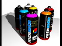
Montana Paint Spray Can 3D Model
...can spray paint graffiti cap model aerosol freon ozone pressure container mtn art montana paint spray can 3d model...
3ddd
$1
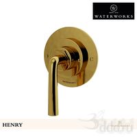
Henry Pressure Balance Control Valve Trim
...henry pressure balance control valve trim
3ddd
waterwarks
henry pressure balance control valve trim
3ddd
$1

Набор картин и декоров для стен
...металлических пластин; - пара картин "right and left hand pressure points gold leaf " в рамках из дерева цвета...
3ddd
$1
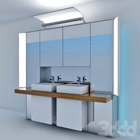
Duravit Mirrorwall MW 9834
...duravit http://www.duravit.com/website/homepage/products/product_overview/series/mirrorwall.com-en.html/p-108955 mirrorwall mirrorwall 4 mirror doors (below including pressure lock), 1 double mirror door including 12 detachable wooden...
3ddd
$1
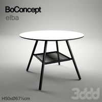
Elba
...garden table (for in and outdoor use), white high pressure laminate with black inner core/matt black structure...
3d_ocean
$15

Steam iron
...iron 3docean bosch cloth electrolux flat houseware iron ironing pressure product samsung siemens steam steam iron steam irons tefal...
3d_ocean
$12
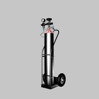
oxygen cylinder
...grey isolated lab life metallic nautical object ocean oxygen pressure recreational regulator research science silver steel tank valve 3d...
3d_ocean
$6
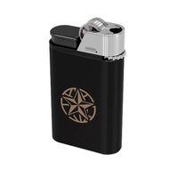
lighter
...lighter
3docean
flame flammable fluid gas lighter liquid metal plastic pressurized
lighter texture map included.
3d_ocean
$25
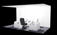
Mine Control Room : A1
...control room dial gauge joystick lever mine nuclear office pressure science originally modeled for a mine, this is the...
3d_ocean
$5

Moka Pot- Coffe Maker
...food home house italian java low poly machine maker pressure robusta stove top 3d moka...
Sensor
3d_export
$42

Vanguard III Satellite 3D Model
...3d model 3dexport project vanguard rocket navy satellite optical sensor weather relay transmitter space orbit vanguard iii satellite 3d...
archive3d
free
Vent 3D Model
...cooking hood cooker hood kitchen equipment vent shindo pallada sensor 60 b bg 4etc n220216 - 3d model (*.gsm+*.3ds)...
3ddd
$1

Mediclinics OPTIMA M99ACS
..., mediclinics , optima сушилка для рук mediclinics optima m99acshttp://www.mediclinics.com/optima-sensoroperated-hand-dryer-m99acs ...
3d_ocean
$6

Office Ceiling Panels
...4 fluorescents, hidden light, speaker, fire – gas dedector sensor square plates holes....
3ddd
$1

ESTILUZ BUTTON T-3305 / T-3306
...to the tasks it will be lighting. the tactile sensor switches each point of light on and off individually....
3ddd
free

Elica Celestia
...47cm diameter 3 speed illuminated 'magic wand' touch button sensor + boost 1 x 40w halogen lamp + 3...
3ddd
$1
Shindo Aliot sensor 60
...вентиляцию)
жировой фильтр:
алюминиевый рамочный
освещение:
2 галогеновые лампы x 20 вт
страна торговой марки:
южная корея
cg_studio
$89

BMW M3 cabriolet 20083d model
...cars bmw m3 cabriolet coup? deutch car pak control sensor caliper vray sport 2008 rims convertible .3ds .max -...
3ddd
$1

Вытяжка Shindo Pallada sensor 60 B/BG 4ETC
...ольный, индикатор загрязнения
максимальный уровень шума 52 дб
антивозвратный клапан есть
вес 18 кг
дополнительная информация часы
3ddd
$1

Armani Casa- dressing table (coiffeuse)- GLAM
...no thickness. the lighting goes on with a motion sensor on the mirror, so the user only has to...